Design and layout in plating lines - Part 1
Design and Layout in Plating Lines
Part 1
Abstract:
Plating facilities constantly strive to maximize the utilization of their workshop space and human resources. In this regard, the design and layout of the plating line play a significant role in achieving optimal efficiency and productivity. By appropriately designing the plating line, one can not only estimate the required equipment but also gain a better understanding of the line’s capacity and meet the customers’ requirements effectively. This article aims to provide practical solutions for controlling the plating process, enhancing the efficiency of each stage, and achieving standardized workshop conditions to increase human resource productivity. In the first part of this article, general concepts will be discussed, followed by a more detailed exploration in the subsequent sections.
Introduction:
When designing a plating unit, various dimensions of the production line activities and the functioning of each section must be examined. Therefore, it is better to have appropriate answers to the following questions from the outset:
1. Is the allocated workshop space for the plating process capable of accommodating the desired production output? To achieve the desired production output, equipment such as tanks, jigs, rectifiers, etc., will be required in different sections of the line. Is the available workshop space sufficient to accommodate this equipment?
2. How is the distribution of tasks among human resources in each section? What are their movement paths, and do these paths intersect with each other?
3. Do the process components require specific preparatory or finishing processes, and have the necessary provisions been made to meet these requirements in the line?
4. Is the required quantity of electricity, water, etc., available, and have the relevant considerations been made for unforeseen incidents?
5. Have environmental considerations, as well as personal health and safety, been taken into account?
Certainly, there are other questions that need to be addressed to achieve ideal conditions, but the ones mentioned are perhaps among the most crucial. Considering the commonality in suitable responses to the questions raised, the importance of design and layout in plating lines becomes evident. The layout of the line, tailored to the type of process and the operational mode of the line, can encompass various scenarios. Plating lines are generally classified into three layouts:
1. Manual
2. Semi-automatic
3. Fully automatic
The arrangement type in each of the mentioned cases, according to the nature of the piece and the desired coverage type, will have its own distinctive features, which will be elaborated and summarized below.
Line layout in manual mode:
As the name suggests, in this mode, pieces are manually moved along the line by operators. Hence, these lines are operator-centric, and their role significantly impacts line efficiency. The primary challenge in manual lines is selecting the shortest path for transferring pieces to ensure the highest possible quality throughout the machining process, from preparation to finishing stages. In this regard, the time intervals for each process, such as sufficient time for warm degreasing, rust removal, acid washing, etc., are entirely dependent on the operator’s performance accuracy. If there is any delay during operations (whether earlier or later than the scheduled time), it will inevitably have a direct impact on the final quality of the work. Therefore, the necessity of designing line layouts in a manual mode dictates not only meeting the required machining conditions for the pieces but also structuring the operator’s movement path to prevent any errors and fulfill the time intervals for each process.
In general, it must be said that manual layout receives less attention in today’s industrial world, except for executing specific coatings where low volume, lightweight pieces, or diverse coatings for a piece are desired. This is because the performance of the line relies heavily on operators, and the likelihood of human errors is high. Additionally, there are risks such as chemical splashes and exposure to toxic gases for workers. Other significant disadvantages of manual coating include higher material and energy wastage, low production speed, waste, and rework due to human errors.
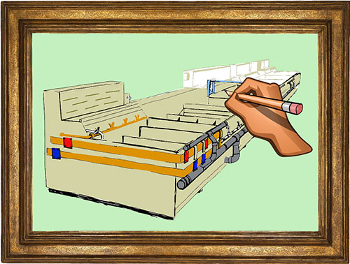
It is worth mentioning that in manual lines, depending on the type of process, layouts such as U-shape, spiral, etc., can also be utilized. Figure 1 illustrates images of manual coating units.

Line layout in semi-automatic mode:
Essentially, it’s the same as a manual line with the difference that piece movement along the line is done by crane or conveyor, primarily controlled and directed by the operator. In this method, control over some coating parameters may be carried out by programmable control systems. The most significant features of this type of line, compared to manual coating lines, include:
Reduced labor requirement, increased production speed, less material wastage and losses, and reduced energy consumption.
This method is primarily used for coating heavy pieces or when the capital required for fully automatic line setup is not available. This is because, by using a crane system, more pieces can be introduced into the line per cycle, thus increasing line efficiency compared to manual lines. Additionally, due to the crane’s use, larger pieces can also be moved along the line.
The layout of vats in this method can also be varied but mostly arranged linearly, with vats of similar shapes placed side by side without gaps. Generally, the layouts employed in these types of lines largely depend on the piece transfer system along the line. For example, if the crane system covers the entire workshop area, layouts like U-shape, perimeter (along the walls), etc., can be used.
Non-linear layouts are common in processes related to aerospace, turbo compressors, and other equipment and parts that possess specific engineering characteristics in terms of geometry and alloy composition. This allows easier access to supplementary processes. Figure 2 illustrates an example of a nickel thick coating unit on turbo compressor parts. The weight of the pieces for coating on this line ranges from 30 to 300 kilograms, hence the need for a crane system for piece transfer.

It’s worth mentioning that in our country, this type of layout is mostly used for processes such as anodizing aluminum profiles, phosphating, and in rare cases, nickel-chromium plating. Additionally, in these types of lines, depending on the designed system, process times and other factors affecting them can be adjusted by operators or controllers.
Line layout in fully automatic mode:
If the line needs to operate on a full-time basis (24 hours a day, seven days a week), full automation should be utilized. Although this mode of operation can also be achieved in manual and semi-automatic lines, the presence of operators within the line entails certain requirements that disrupt process continuity. In fully automatic lines, operators are only involved in loading pieces onto jigs (templates). Once the jigs are placed at the defined location at the beginning of the line, they are moved along the line by transporters. An interesting point observed in the design of automatic lines today is the use of robots in the process of placing pieces on jigs. This eliminates another stage dependent on operators and ensures the continuity of line performance throughout the day and night.
As mentioned, in these types of lines, the process of coating pieces will be automatic and without operator intervention. Furthermore, to control parameters such as temperature, pH, and flow density in the process, a programmable logic controller (PLC) control system is utilized. Additionally, there is the capability to analyze the line’s solutions online and charge them with the necessary additives. In such lines, real-time process monitoring is even possible. For example, instant information about the pieces’ positions can be obtained, and if the coating specifications are not met, parameters such as flow density can be adjusted accordingly.
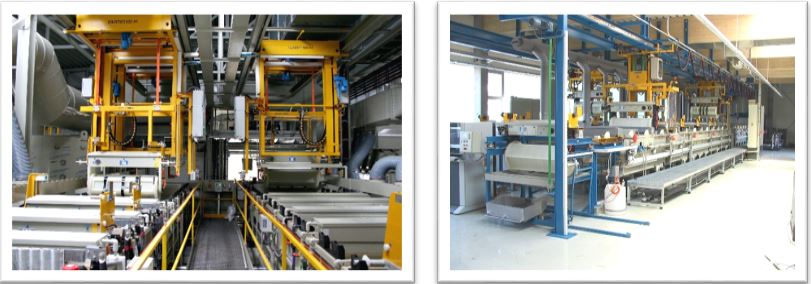
The linear layout is the most popular type of layout in fully automatic lines because it minimizes the distance for transferring pieces from one stage to the next, thus maximizing the utilization of workshop space. In Figure 3, examples of common layouts in fully automatic coating lines using the barrel method are illustrated.
Among the most significant advantages of automatic lines is the capability to coat a large number of pieces during a single workday, reaching thousands of times the throughput compared to manual lines, especially for coating plastic parts. Additionally, since all parameters governing the processes are continuously controlled, the quality of coating for all pieces is almost uniform, and the results obtained are repeatable. Achieving this in manual lines, which are operator-dependent, would require much more meticulous control, particularly for significantly lower throughputs.
Other advantages of fully automatic lines include reduction in chemical consumption due to minimized waste, lower energy consumption, decreased overhead costs and production costs, and easier management of wastewater discharge.
On the other hand, perhaps the biggest obstacle to setting up fully automatic lines is the need for a significant initial investment. Therefore, considering that these lines have a high production potential, they should be pursued when a high throughput is desired and customer orders are guaranteed every day. In other words, the economic justification for launching fully automatic coating lines lies in high throughput, and otherwise, their use is not recommended.
In a broad overview, the number of modern fully automatic coating units in the country is very limited (less than ten cases), while the needs of the coating industry dictate that there should be more of such units. This would enable competitiveness in the market with appropriate final prices. It’s worth noting that with manual lines, the final prices will be significantly higher because the workshop’s profit needs to be met with fewer coated pieces. This would necessitate a higher desired profit per piece compared to the standard amount.
Examples of Line Layouts:
To better illustrate the subject, an example regarding the arrangement of tanks in different configurations is presented here. For this purpose, a nickel-chromium plating line for iron parts is considered. The sequence of stages in most standard lines for coating iron parts with nickel and chromium layers is as follows:
1- Hot degreasing
2- Oxide removal
3- Electrocleaning
4- Neutralization (activation)
5- Initial nickel plating (if necessary)
6- Bright nickel plating
7- Chromium plating
In each of the mentioned stages, a number of tanks are used for the rinsing process, proportional to the available workshop space. If we want to design the layout according to the order and sequence of these stages, we will have various options, some of which are discussed here:
Parallel Line Layout:
In this configuration, tanks related to the main stages are placed on one side, and rinse tanks are placed on the opposite side. Figure 4 schematically shows a part of this layout. Additionally, the operator’s movement path for manual plating is indicated by green lines.
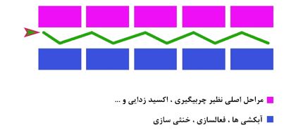
This layout has its own advantages and disadvantages, some of which are mentioned here. One advantage is the limited operator movement path and the absence of secondary aisles. This allows the operator to work in a concentrated manner within a defined area. Also, due to the two-sided layout, the line is not excessively long, reducing operator fatigue. For ventilation systems, a central collector can be used, with branches applied to each desired section. Moreover, issues related to the piping of input water and wastewater will be less challenging. However, the biggest drawback of this layout is related to material loss and environmental consequences, as during the transfer of parts from the main tanks to the rinse tanks, some of the solutions inside the tanks are transferred to the operator’s aisle through parts, exacerbating if dip time requirements are not met. It’s worth mentioning that due to the difficulty of transferring parts with cranes in this type of layout, it is mostly used in manual lines.
Linear Layout:
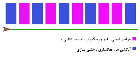
In this configuration, all tanks are placed one after another in a straight line. Figure 5 schematically depicts a portion of this type of layout.

The major advantage of this layout is a significant reduction in material spillage during the transfer of parts from one tank to another, resulting in a noticeable decrease in the environmental impact associated with the line. However, it is ideal to imagine that in manual plating, the operator does not lean towards the aisle after removing the part from each tank but goes directly to the next tank. Another advantage of this layout is that the operator’s work speed will be higher since the part is continuously moved in a linear direction. Additionally, there will be fewer challenges in terms of line facilities such as cable routing and piping. On the downside, the most prominent disadvantage of this layout is the longer length of the line and therefore the need for more operators compared to the parallel layout. Approximately, the length of this type of line will be nearly twice as long as the parallel layout.
As previously mentioned, this type of layout is very common in semi-automatic and fully automatic lines, with the difference that in manual mode, the tanks are arranged side by side along the length to allow the operator access to the entire working space of the tanks. However, in semi-automatic or fully automatic modes, the tanks are arranged side by side along the width. In Figure 6, a linear layout for this scenario is illustrated.
It should be noted that the sequence of plating stages in automatic plating lines is not necessarily similar to manual lines and will be tailored to maximize the efficiency of the line based on the designed program.
Layouts for the Environment:
The layouts mentioned earlier are common and classic cases in plating lines, but depending on the available workshop space, other layouts can be utilized. For example, when faced with limited workshop space, the layout related to the desired process can be as shown in Figure 7.
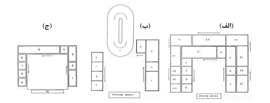
As observed, in these situations, environmental layouts allow for the utilization of all workshop space. Each of the layouts shown in Figure 7 has its own characteristics. In situation (a), by combining two U-shaped layouts, conditions are created for two types of processes. For example, in the case of plating on plastic parts using this layout, the inner part of the line can be used for pre-treatment of plastic parts, while the outer part can be used for final plating (copper/nickel/chrome).
Similarly, in situation (b), by utilizing movable cathode technology, the required human workforce can be reduced. Situation (c) is suitable for conditions where the plating process involves special operations such as masking or machining because this layout allows for the use of the central workshop space for any required supplementary operations on the part at any time.
It is worth mentioning that due to the extensive nature of the line in these layouts, a suitable layout must be chosen to prevent intermittent use of the crane system and damage to it. Therefore, U-shaped layouts are prioritized.
Summary:
Different indicators must be considered during the design of a plating line to maximize workshop space and human resource utilization while minimizing environmental impacts. In manual lines, challenges in meeting these criteria will be more significant due to their operator-centric nature, leading to a preference for establishing fully automated lines in advanced countries. This article provided a general overview of common layout types and briefly discussed their pros and cons. In the next section, efficient designs and layouts will be presented in detail.


