


مقالات - فیلتر
The importance of employing standard and efficient equipment in improving the quality and efficiency of the plating process cannot be overstated.
Part 2: Filtration
Reza Mehtar Ghorehdaghi (MSc in Corrosion and
Materials Protection) Peyman Samadi (MSc in Materials Engineering and Metallurgy)
Abstract:
In the previous section, the use of standard and efficient equipment was discussed, focusing on various methods of creating turbulence in the solution and the objectives of employing them in plating lines. One of the significant effects discussed was the creation of intense flows within the solution. While such turbulence is inevitable for achieving desirable practical results and ensuring uniform conditions throughout the solution, it may lead to the suspension of impurities particles present in the solution and the possibility of their co-deposition within the coating. This implies an increase in the number of rejected parts in quality control inspections. Filtration is the most effective method in plating lines for removing impurities and suspended particles from solutions. Therefore, considering the importance of filtration and its effects on coating quality, this article is dedicated to this topic.
Introduction:
Filtration of plating solutions may have been among the first necessities that took shape in the minds of platers from the very beginning, as the deposition of any contamination on the final coating and the resulting surface defects were unacceptable. On the other hand, creating turbulence within the solution, resulting in uniform distribution of concentration, heat, and preventing the passivation of anodes, thereby accelerating the process of supplying metal ions from their dissolution, were among the other benefits of using filtration systems that became apparent over time. Throughout the history of the plating industry, filter manufacturers and equipment suppliers have focused on various filtration systems based on the type of solution and the nature of impurities present in it, placing the development of these systems at the forefront of their research and development units to maximize their efficiency. A look at the evolution of filter designs reflects the efforts made. Figure 1 illustrates examples of filters used in the mid-20th century, while Figure 2 presents images of modern filters.
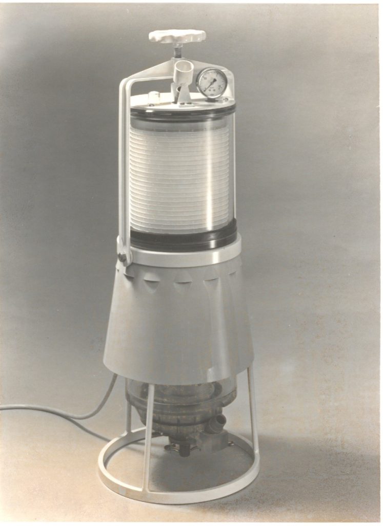
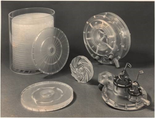
Figure 1. Example of filters used in the mid-20th century
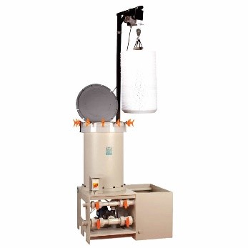
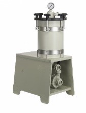
Figure 2. Examples of modern filters
Today, most filter manufacturers offer their products in three main categories based on the type of filter media: disk, cartridge, and bag filters. It is worth noting that other types also exist for specific purposes, such as filter presses used in wastewater treatment lines to separate solid deposits and clots from water. Essentially, the structure of filters consists of a pump, a reservoir, and the filter media. The operation principle is as follows: the solution is directed into the reservoir by the pump and, after passing through the filter media, it is injected back into the main tank. The most common types of pumps are mechanical and magnetic, as depicted in Figure 3. It is worth mentioning that magnetic pumps have a longer lifespan due to the absence of contact parts with the solution (mechanical seal).
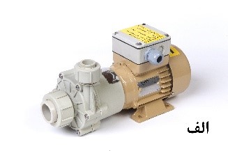
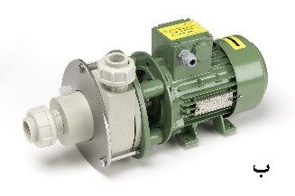
Figure 3. Magnetic pumps (a) and mechanical pumps (b)
Continuing, a brief introduction to and application of each of the mentioned filters is provided:
Disk Filters: These filters consist of plastic disks made of polypropylene, along with paper or polypropylene fabric filters placed between the disks. Figure 4 provides an image of a disk filter, along with a schematic of its interior.
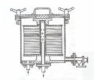
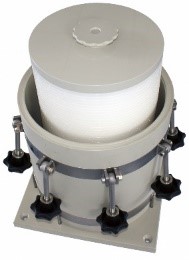
Figure 4. Image of a disc filter
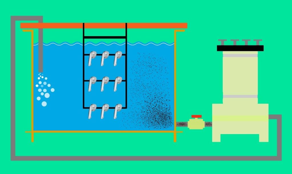
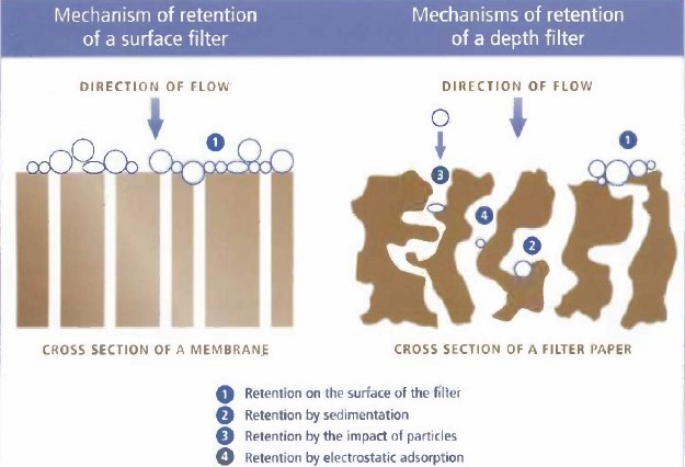
The mechanism of particle removal by this type of filter is illustrated schematically in Figure 5. As shown, four mechanisms for the removal of impurities by the filters inside the reservoir have been envisaged. In the first scenario, which is the most probable mechanism, large impurities are absorbed onto the micron-sized holes on the surface of the filters, making it difficult for subsequent particles to pass through. The second scenario involves impurities settling within the fabric of the filters. In the third scenario, impurities are trapped within the filter structure due to collisions with other particles. Finally, the fourth predicted mechanism, primarily applicable to very fine particles, involves absorption by electrostatic forces.
Mesh sheets are usually made of fabric material with a mesh size of around 50 microns or thick paper with a mesh size of 5 microns. It’s worth noting that carbon paper mesh sheets also exist, which are sometimes used to simultaneously remove both mineral and organic impurities.
Cartridge Filters: In this type of filter, cylindrical plastic core elements with abundant surface perforations are used. Figure 6 shows images of these filters and the cartridges used in them.
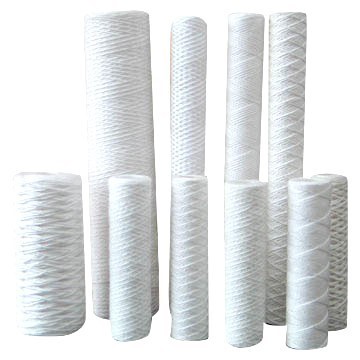
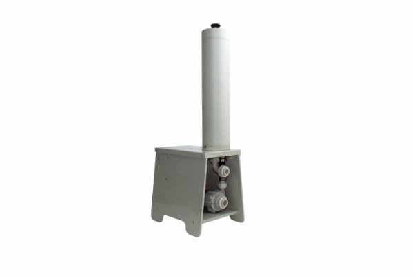
Figure 6. Images of a cartridge filter along with its meshes
The outer surface of the cartridges is coated depending on their intended use. The most common coating for cartridges consists of a collection of fibers resistant to chemical substances. Through this meshing, a wide range of impurities can be removed. The mechanism for removing particles by cartridges is almost identical to the mechanism provided by disc filters containing mesh sheets.
Bag Filters: The primary feature of bag filters is the smooth flow rate of the solution passing through them, allowing sufficient time for the removal of impurities that require time for removal. Figure 7 shows images related to these types of filters.

Figure 7. Images of bag filters
Filters with bags have diverse applications and are used in various situations depending on their intended use. The most important applications of this type of filter include:
1. Filtration with empty bags: Recommended for the initial filtration of phosphate solutions, dewatering, and in wastewater treatment systems. Key features of filtration using empty bags include high capacity for holding removed impurities and low maintenance costs.
2. Filtration with carbon-containing bags: This method aims to remove organic contaminants present or generated in the bath during the plating process, often resulting from the breakdown of additives for various reasons. It is worth noting that the smooth flow in bag filters enhances the efficiency of carbon particles.
3. Filtration with bags containing hydrophobic fibers for removing fat and oil particles: This filtration method removes oily stains present in solutions. Removing oil from grease traps and related wastewater contributes to reducing the COD index in the overall wastewater analysis.
4. Filtration with fiber-containing bags for specific purposes: In cases where gel-like deposits are present in the solution, this system can be used. One of the applications of this filter is in acidic copper solutions, which always contain suspended particles of quadrivalent copper. The high effective surface area of the fibers is the most important parameter in increasing the efficiency of removing desired chemical compounds.
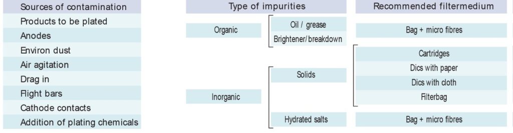
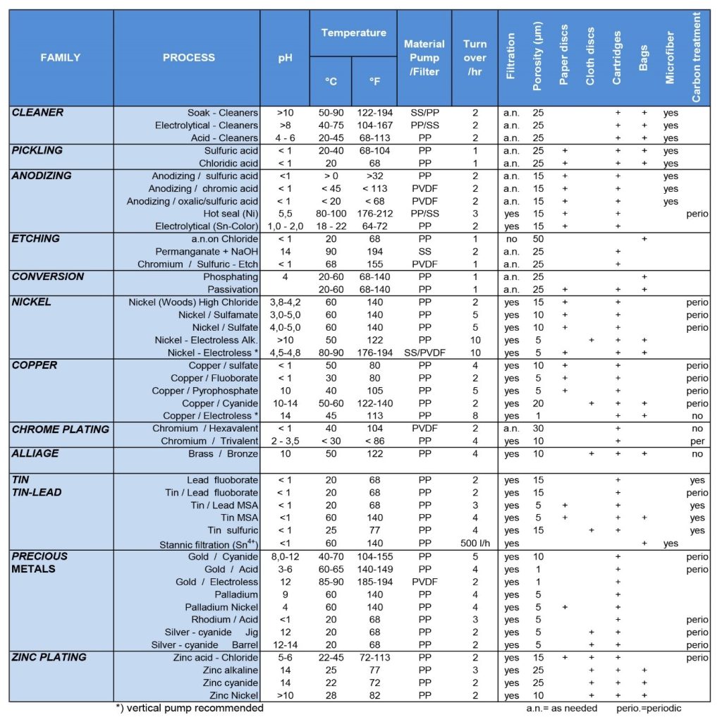
In Table 1, the application categories of each of the proposed filters are presented.
Consideration of the following factors can contribute to choosing the most appropriate filter:
1- Filter mesh size (filtration porosity)
2- Nature of contaminants
3- Level of contamination
4- Desired flow rate
5- System pressure
6- Method of filter deployment (continuous or intermittent)
7- Type of solution intended for filtration
Since the most effective indicator in removing solid impurities is the size of the filter mesh, its role in filtration efficiency is further elucidated below.
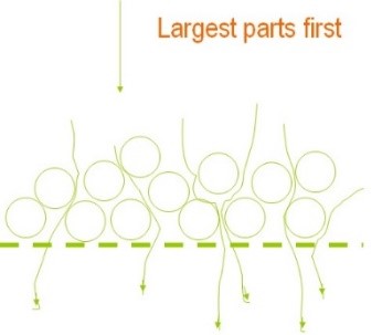
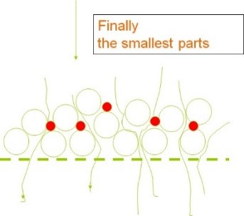
The mesh size, defined in microns, is proportional to the type of solution, primarily determined by plating material suppliers. If particles in the solution are larger than the filter mesh, they will be directly removed (Figure 9). Consequently, the likelihood of removing smaller particles increases due to the blockage of larger particles in the mesh. Often, particles have irregular geometry, and their absorption by the filter mesh leads to the phenomenon of “bridging” (Figure 10).


As depicted in Figure 10, the “bridging” phenomenon can occur when more than two suspended particles simultaneously get lodged in a single pore.
When a particle is trapped in a filter pore (Figure 11), the pore nearly closes, subsequently enabling the removal of finer particles. It is worth noting that initially, larger particles are removed, but there is still a possibility of smaller particles passing through. Over time, as the layer resulting from the removal of larger particles thickens and cake formation occurs on the filter mesh, medium-sized and ultimately very fine (micron-sized) particles will also be removed (Figure 12).
It should always be kept in mind that the passage of a solution containing suspended particles through the filter will result in pressure drop due to the deposition of impurities on the filter mesh. On the other hand, the volume of empty space (void spaces of the filter) is always of paramount importance. A filter with the highest void space is the most desirable state, ensuring longer lifespan and lower initial pressure drop. The schematic illustration in Figure 13 demonstrates the impact of void space volume on the percentage of impurity particle retention by the filter.
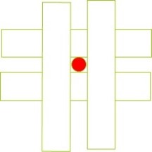
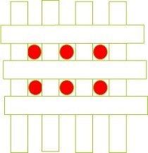
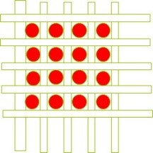
Figure 13. Effect of pore size reduction on the efficiency of removing impurity particles from the solution
The flow rate is also influenced by the size of the filter pores, which will be discussed below in terms of improvement. In Figure 14, the effect of increasing the free area of a disc filter (the area through which the solution passes) on the efficiency of impurity removal from the solution is illustrated. It is evident that the greater the impurity retention capacity of the filter, the longer its useful life will be.
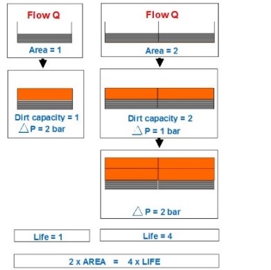
In Figure 14, the orange areas indicate the cake formed inside the filter. It can be observed that doubling the effective area of the disc filter increases its lifespan fourfold. Additionally, in Figure 15, the effect of the geometry of the cartridge’s outer surface on the effective filter area is shown. The protrusions on the outer surface of the filter result in an increase in the effective filter area from 0.05 to 0.5 square meters in 10-inch cartridges.


Figure 15. Two different cross-sections of a cartridge filter
To select the appropriate type of filter, it is necessary to consider it from both an economic and technical perspective, which will be discussed below.
Economic considerations in selecting a filter and the associated provisions:
Perhaps the best example to illustrate the importance of considering economic factors in choosing the type of filter is the iceberg principle (Figure 16). According to this principle, the tip of an iceberg, which emerges from the water’s surface, constitutes only a small fraction of the total volume of the iceberg, while the majority of the iceberg remains hidden underwater and invisible. The relevance of this principle to filter selection lies in the fact that the initial cost customers pay at the time of purchase is like the tip of the iceberg, covering about 10% of the future expenses. Initially, this may seem like the main criterion for customers when making a purchase decision. However, energy costs, production losses due to filter failure and line shutdowns, as well as repair and maintenance, account for about 90% of the costs associated with the filtration system in the future if an incorrect choice is made, burdening the end-users.

Therefore, it should always be remembered that the price of the filter should not have the greatest impact on the buyer’s final decision, and attention should be paid above all to future costs.
Technical considerations in selecting a filter and the associated provisions:
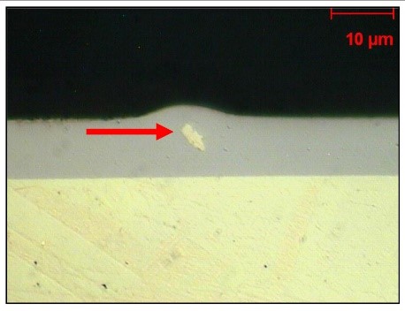
Preventing surface roughness is likely the primary reason for filtering plating solutions today. In Figure 17, an example of a suspended particle trapped within a coating, ultimately leading to surface roughness, is illustrated.
In addition to suspended solid particles, platers must also contend with other organic and mineral contaminants that enter the solution due to residues left inside components from previous stages. Furthermore, achieving better coverage with less risk of burning allows for cleaner baths. Allowing such contaminants to exist in the bath compromises the properties of the coating. Therefore, continuous or intermittent carbon filtration or low-voltage plating often removes such contaminants.
When designing a filtration system, it’s essential to first determine its main objective, which could potentially be one of the following:
1. Achieving the highest quality surface finish with smoothness and high gloss.
2. Obtaining suitable physical properties in terms of coating particle size and resistance to abrasion and corrosion.
3. Achieving maximum efficiency in the plating process and precise control over parameters such as covering power, plating speed, and the removal of any contaminants.
After determining the objective, the following aspects should be examined before selecting filters and relevant strainers:
– Level of contamination in the solution: Suspended particles in terms of size, type, and quantity, as well as any dissolved organic and inorganic impurities in the solution.
– Required flow rate: The rate at which the solution needs to circulate per hour to achieve high transparency.
– Filtration frequency: The desired interval for filtering the solution and removing impurities from it.
In the following, we will examine each of the mentioned items:
The level of contamination in the solution:
In general, sources of contamination in plating baths include the ingress of solutions from previous stages through drag-in, dust, anodes and their bags, sludge and metal fines within the parts, handling equipment along the line, required water, and the air used to create agitation in the solution. To effectively remove these contaminants, the filtration system must be designed considering the type and quantity of impurities present in the plating bath. The importance of this lies in the fact that a filter with insufficient capacity to hold contaminants within itself will require more frequent cleaning and servicing in shorter intervals. Moreover, the sudden pressure caused by the accumulation of impurities inside the filter media can lead to increased stress on the pump and ultimately damage its components. Therefore, by reducing the ingress of impurities into the filter, the costs associated with filter and pump maintenance can be significantly reduced. Even after cleaning and rinsing stages, some solid particles and contaminants adhere to components, jigs, and barrel tanks. Hence, these impurities will be introduced into the plating baths due to the mentioned factors. Among these, the level of contamination entering the baths is directly related to the type of part, the plating method (rack or barrel), the efficiency of part cleaning, and the cleaning cycle of the parts. It is worth noting that periodic inspections can minimize the ingress of some impurities into the baths. For instance, inspecting the environmental conditions around the tanks, such as walls and ceilings, is one of the initial solutions to prevent contamination from entering the tanks. In plating lines, various parts undergo plating processes, and therefore, for the baths to be free from any kind of contamination, the filtration system must be designed to operate optimally under the highest line efficiency conditions and handle the toughest and most complex parts for cleaning and rinsing. In this regard, the level of contamination entering the barrel lines is high because adequate rinsing is not possible in this method. Therefore, continuous filtration in automatic barrel lines must be designed to minimize downtime due to repairs. The ingress of impurities into the plating baths can often be reduced by optimizing the preparation process. For example, hot degreasing by immersion is very suitable for machined parts. Additionally, creating agitation in the solution simultaneously with the overflow system significantly helps remove oil from degreasing solutions. It should be noted that oil quickly contaminates filter media. Moreover, increasing the efficiency of oxidation removal will also reduce the ingress of impurities into the main solution. Overflow systems with low overflow rates significantly help reduce the ingress of impurities into subsequent baths. Essentially, due to the nature of the cleaning process, the presence of contamination in the solution (both organic and inorganic) is inevitable. It should always be remembered that conventional filtration will not remove impurities such as organic compounds, additives, and oils, and the only method to remove them is the use of activated carbon. On the other hand, some plating baths, such as bright nickel, produce organic by-products during the plating process. Since the rate of production and increase in organic and inorganic impurities in the bath is not the same, transferring the solution to a secondary tank through a filter pump and cleaning the main tank will be effective because this method will remove both types of contaminants. Examining the transparency and flow rate of the solution, as well as the surface quality of the coating, requires comprehensive filtration and subsequent carbon treatment. Additionally, the presence of contaminants in the bath can be evaluated by testing Hull cell test samples. The presence of pitting, poor adhesion, and spotted coating in this test can be an indicator of the need for carbon treatment of the solution.
Required flow rate:
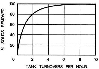
A high flow rate is a crucial indicator for quickly removing impurities from the solution and preventing their deposition on the parts. Plating in a solution free from impurities is the most ideal condition, achievable only in laboratory environments. In industrial settings where we deal with high-volume solutions, the presence of some impurities is unavoidable, and this must be accepted. However, continuous filtration can create the highest quality in production by keeping the level of suspended solid particles low in the solution. As shown in the graph presented in Figure 18, complete circulation of the bath solution 4 to 5 times results in removing more than 90% of the suspended solid particles in the solution, assuming no other solid particles enter the bath through external factors.
Since in most cases where filters are installed, the rate of impurity ingress is much higher than the amount removed by the filter, the level of impurities and solid particles in the solution increases gradually over time. To overcome this phenomenon, filtration must be continuous, even during periods when plating is not being carried out. Figure 19 shows that due to the accumulation of removed impurities inside the filter, its flow rate decreases. Additionally, Figure 19 indicates the decrease in the flow rate passing through the filter as a result of the accumulation of removed impurities based on its performance day by day over a week. For example, at point A, where the filter starts operating, we have the highest flow rate of solution passing through the filter alongside the lowest pressure. This is while after four days (point B) and due to the clogging of the filter pores, we observe a decrease in the flow rate passing through the filter and an increase in internal filter pressure.
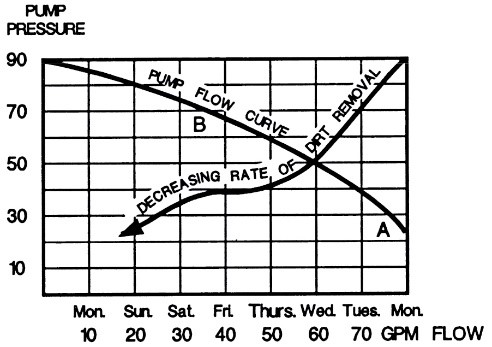
This decrease in the filter flow rate itself can be an indicator of long downtime periods when cleaning the filter. Additionally, from this graph, it is evident why platers may experience roughness during filter downtime. It should be noted that when the filter is cleaned, at the start of solution circulation, a high flow rate will be experienced, which is why settled particles on the bottom of the tank due to the intense agitation will be suspended in the solution. Therefore, it is recommended to refrain from plating parts until the level of contamination is reduced through filtration to an acceptable level after cleaning the filter.
Filtration Interval:
Ideally, plating should take place in solutions free from any impurities. The quickest method to achieve high solution transparency is to transfer it from the main tank to a secondary tank using a filter pump. It should be noted that continuous filtration is recommended to simultaneously maintain solution transparency and uniform coating quality. Table 2 provides the required specifications for filtering common solutions in surface finishing processes. As seen in Table 2, for most plating solutions, the flow rate of solution passing through the filter must be such that the total turnover of solution inside the tank through the filter (turnover/hr) reaches two to three times per hour. This means, for example, a tank with an approximate volume of 3800 liters requires filtration with a flow rate of 7000 to 12000 liters per hour. However, platers should bear in mind that for complete removal of solid particles, according to the graph presented in Figure 18, a minimum of 10 complete turnovers of the solution will be required.
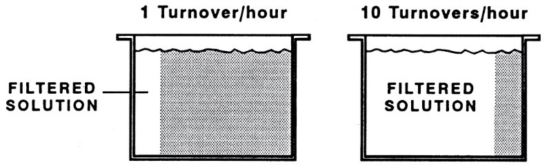
To further illustrate this concept, let’s consider an example. Suppose we have a tank with a volume of 380 liters, and we want to filter the entire solution once per hour (1 turnover/hr).
In this case, the flow rate required to achieve one turnover per hour would be:
lit/60 min = 6.3 lpm 380
This means that 6.3 liters of solution will pass through the filter every minute. Therefore, after 5 minutes, approximately 32 liters of the solution will have passed through the filter (about 8% of the total volume).
However, if the filter flow rate is increased to 10 times this amount, we would have:
lit/ 60 min = 63.3 lpm 380×10
With this flow rate, after 5 minutes, approximately 320 liters of the total volume will have been filtered (about 80% of the total volume). This comparison is schematically illustrated in Figure 20.
Installation Tips for Filters:
The method of installing a filter significantly impacts its lifespan. Therefore, in this section, we’ll mention some practical tips for installing filters.
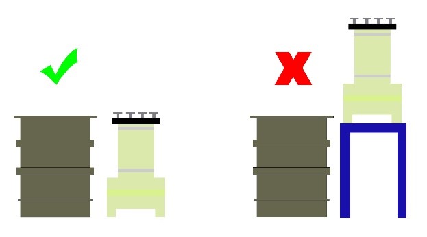
1. It is recommended to avoid placing the filter at higher positions relative to the solution level to prevent pressure build-up on the filter pump and its overheating. This is schematically shown in Figure 21.
2. The suction pipe should be of the shortest possible length, and if feasible, use an appropriate hose (spring-loaded).
3. If a piping system is used, try to avoid using elbows, bends, and fittings in the suction part as much as possible.
4. The suction pipe and solution inlet must be placed at opposite points and, if possible, away from each other in the tank.
5. Periodically, the filter cartridges should be removed and washed with diluted acid such as 20% sulfuric acid, followed by thorough rinsing to remove any remaining acid residue. This is to prevent the filter pores from being clogged, which can lead to pressure build-up on the pump.
6. The filter should never operate dry, and utmost care should be taken during priming to ensure that the outlet solution is free of air bubbles.
7. The rotation of the filter motor impeller should be periodically checked to match the arrow on the motor housing. Also, ensure that the filter’s power input is never two-phase or single-phase.
8. Care must be taken during the filter body washing process to avoid water splashing onto the electric motor.
9. In cases where the filtration solution contains compounds that form deposits when cold, it is recommended to turn off the filter first. After warming the tank, inject the heated solution into the filter. After ensuring that the deposits are dissolved, proceed to turn on the filter.
10. The use of phase control, non-metallic, and other protective equipment for the power input is recommended.
11. The operator should regularly monitor the pressure gauge display on the tank, and if it reaches 1.5-2 bars, promptly proceed to replace or wash the tank and disk filters.
Summary:
Today, water treatment professionals bear significant expenses to procure essential raw materials such as salt and anodes, ensuring the highest level of purity. They even produce solutions using distilled water or filtered and hardness-treated water. There is no doubt that all these efforts are aimed at achieving highly pure and effective solutions. Therefore, it is essential to protect and control this valuable solution every day and every moment.