IBE

فارسی

شرکت‌های همکار

General electroplating materials and equipment

Electrophoretic varnish

Solution heating and temperature control systems

Plating solution pump and filter

Fully automatic plating lines

Fully automatic plating lines

Ecotechno Italy

Plating materials for precious metals

Articles - Heating and Cooling Systems

The importance of employing standard and efficient equipment in improving the quality and efficiency of the electroplating process.
Heating and cooling systems in plating lines


Reza Mehtar Ghorehdaghi (MSc in Corrosion and Materials Protection)

Peyman Samadi (MSc in Materials Engineering and Metallurgy)

Abstract:

Various parameters affect the speed and quality of chemical and electrochemical processes, including electroplating, among which temperature plays an indispensable role. Generally, throughout a plating line, from preparation to finishing surface work and supplementary processes, we deal with solutions that each have efficiency within defined temperature ranges. Adhering to these specified ranges can significantly contribute to increasing process efficiency and improving the final quality of component coatings. Factors such as process working temperature, acidity or alkalinity of solutions, and the volume of solution required will affect the selection of heating and cooling system types and capacities. Therefore, to ensure the proper functioning and longevity of the system, these considerations must be taken into account. This article briefly touches on the fundamentals of the process, types of heating and cooling methods for solutions, and some practical considerations related to them.

Introduction:

Taking a look at the solutions present in a plating line, we find that almost all existing processes, and in some cases even rinsing processes, require maintaining a specific working temperature. This is because the efficiency and quality of many of these processes change significantly as a result of heating or cooling. These changes can include facilitating preparation processes, improving metallurgical properties of coatings, and creating suitable conditions for related finishing processes. Therefore, temperature variation, due to its wide-ranging function throughout different plating stages, has always been a focal point. The function of increasing or decreasing temperature can vary depending on the type of process and the nature of the solution. For example, in the case of degreasing processes, higher solution temperatures facilitate the removal of oil, grease, and other contaminants from the part more effectively, particularly in situations where parts have geometric complexities making access difficult for operators. As observed, in degreasing processes, increasing the temperature is desirable and beneficial. However, for some other processes such as chrome plating, anodizing, and electropolishing, where solution temperature increases due to the nature of the operation, controlling the temperature and preventing damages caused by it becomes necessary. Similar conditions apply to more general processes like nickel plating. Excessive temperature increase in such cases may lead to additive decomposition, resulting in process failure.

On the other hand, since the use of heating and cooling systems, like other equipment in a plating line, also entails economic consequences, platers are always looking for efficient and cost-effective systems to reduce overall costs. Unfortunately, there have been instances where platers, facing energy constraints or seemingly seeking energy savings, resort to traditional and hazardous methods, which not only result in financial damages such as fires and equipment loss but also pose life-threatening risks. Therefore, when selecting the appropriate equipment, both efficiency and safety should be considered.

In the following sections, we delve into the fundamentals of heat transfer processes, various methods of heating and cooling, and some practical considerations in employing such systems. It’s worth mentioning that the term “heat exchanger” used in the text refers to a system similar to a coil that has a dual purpose and can lead to either increasing or decreasing the solution temperature. This clarification is necessary because in some sources, this term is also used to introduce electric heaters.

Process Fundamentals:

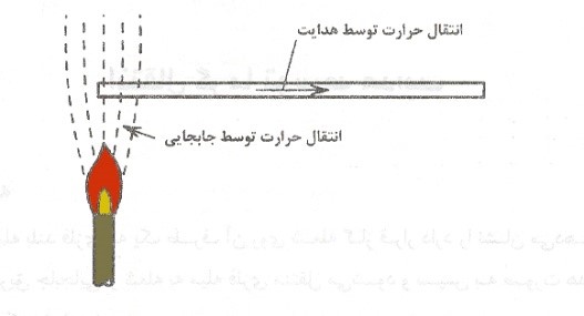
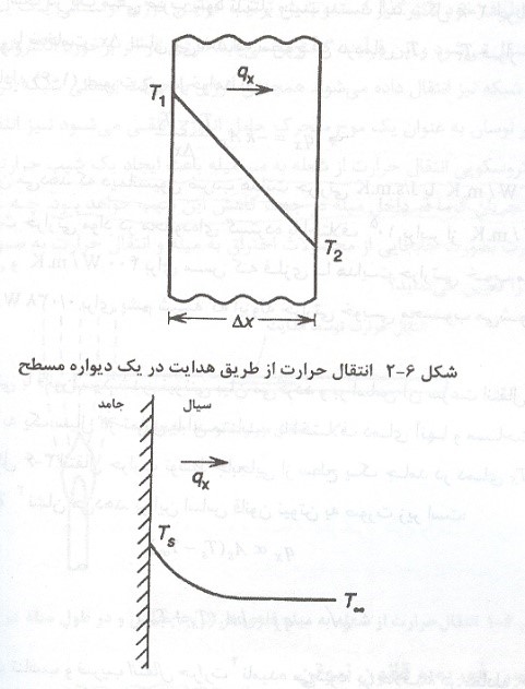
When an object begins to generate heat and its temperature increases compared to other objects nearby, it is referred to as a heat source. As the process environment heats up, the temperature of other objects increases through one of the general mechanisms of heat transfer: conduction, convection, and radiation. In the context of heating systems used in plating lines, heat is transferred to the solution of interest using a combination of these mechanisms. Figure 1 schematically illustrates how a metal rod heats up in the vicinity of a flame.

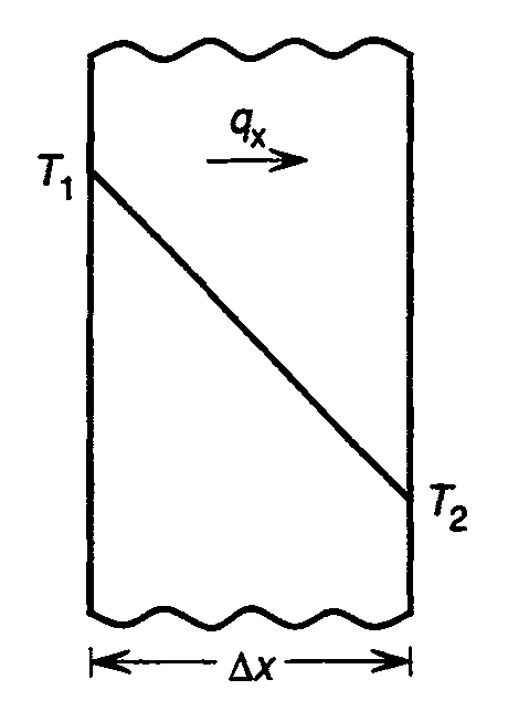
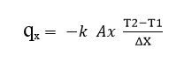
Similar conditions apply to cooling processes, with the difference that the solution to be cooled is placed near a cooling source, resulting in a decrease in temperature due to the existing heat gradient. To better understand this mechanism and the effective surface area of the heater, brief explanations about these mechanisms are provided in the following discussions.

Figure 1. Schematic of heat transfer from a flame to a metal rod

Heat Transfer by Conduction: In this method, thermal energy is transferred from one substance to another through direct contact. It is the most efficient way of transferring heat, allowing a significant portion of the generated heat energy to be transferred to the desired substance. As illustrated in Figure 2, when an object is in contact with a hot environment, heat transfer occurs due to the presence of a temperature gradient.

Figure 2. Schematic of temperature gradient during heat transfer by conduction

As a result of this temperature gradient, heat flows from the side with higher temperature to the side with lower temperature. Heat conduction is described by Fourier’s law, which in one-dimensional heat transfer in the x-direction can be expressed as follows:

In this equation, Ax is the effective area for heat transfer, T1 and  T2 are the temperatures on either side of the wall, and xΔ is the thickness of the wall. The variable  k  is the proportionality constant representing the thermal conductivity of the material, measured in units such as J/s. m.k or w/ m.k The thermal conductivity of materials varies widely, ranging from around 3400 W/m·K for pure diamond, 400 W/m·K for metals like copper, considered to have good thermal conductivity, to 0.038 W/m·K for materials like glass wool, known for their good thermal insulation properties. Hence, using materials with lower thermal conductivity in the construction of tanks can reduce heat loss from the walls. Therefore, materials such as polypropylene (PP) or polyvinyl chloride (PVC), which have lower thermal conductivity, are preferred in the construction of electroplating tanks compared to iron with a soft PVC coating. This way, significant heat loss through the walls and tank bottom can be prevented. In cases where the only solution is to use iron or steel tanks, thermal insulation materials like glass wool should be used to cover the walls and tank bottom.

Heat Transfer by Convection: In this method, physical contact is also utilized for transferring heat energy, but with the difference that here we need an intermediary gas. In the process of convection heating, the heat source warms the gas, causing the lighter gas volume to expand and acquire buoyancy properties. The heated gas moves upward, inducing the displacement of air currents. This phenomenon leads to the movement of the warm gas flow towards colder objects and contact with them, resulting in their temperature increase. Heat convection is described by Newton’s law of cooling, where the rate of heat transfer from the surface of a solid to a fluid in contact with it is proportional to the temperature difference between them and the surface area of contact. According to this law, we have:

qx = h × As × (Ts – T)

 In this equation, h  represents the heat transfer coefficient. Figure 3 schematically illustrates the temperature gradient resulting from heat transfer by a fluid from the surface of a solid (heater) at temperature  Ts  towards a medium with a lower temperature.

Figure 3. Schematic of heat transfer by convection

Heat Transfer by Radiation: The third method of heat transfer is radiation, which, unlike the previous two methods, does not rely on physical contact between the heat source and the object. In fact, thermal radiation is considered a portion of the electromagnetic wave spectrum, the wavelength range of which is illustrated in Figure 4, and like other electromagnetic waves, its propagation does not require a material medium. A clear example of heat transfer due to radiation is the warming of the Earth by solar radiation.

Figure 4. Electromagnetic spectrum

Electromagnetic waves arise from oscillations of electric fields around electric charges, and therefore, all materials emit thermal radiation at any temperature. The intensity of the emitted radiation is related to its wavelength, so a diverse range of temperatures can be created in different frequency ranges. For example, microwave ovens use waves with large wavelengths to heat food, while radio waves with much lower wavelengths are used in medical devices for localized heating of body tissues without causing harm. Ultimately, the phenomenon of energy transfer from heat exchangers occurs through the introduced mechanisms. The capacity of a heat exchanger is evaluated by the amount of energy transferred per unit time. As mentioned in previous sections, the heat transferred is proportional to the effective area in contact with the solution and the temperature difference between them. Therefore, the following general equation can be considered as an indicator of the amount of energy transferred:

In this equation, Q is the rate of energy transfer, A is the effective area for temperature difference and energy transfer.

The coefficient U is a complex function of the heat exchanger’s design type and its operating conditions. Considering that one of the most effective indicators for the proper functioning of heaters is their effective surface area, further explanations will be provided regarding it. Effective surface area and surface power density are crucial variables in designing heaters. The minimum value of the effective area is defined by a concept called surface power density, which ensures that if the allocated effective area for heat transfer from the heater to the solution is less than a specified amount, there is a possibility that the temperature on its surface may increase to very high levels (even up to several hundred degrees Celsius), leading to the decomposition of organic compounds inside the bath or the formation of deposits on the heater’s surface. Therefore, this point must be considered during the design of heaters because increasing or decreasing the surface area of the heaters without considering these limitations not only reduces efficiency but also leads to consequences such as material loss due to heat. Table 1 presents the numbers related to the surface power density index for some electric heaters.

Table 1. Surface power density index for electric heaters with different powers and materials

Please ensure that when using heaters, you pay attention to the relationship between heater power and its effective area

Common Methods for Heating and Cooling:

There are two common methods used for heating solutions. The first method involves directly placing electric heaters inside the solution. The second method utilizes coils, which can be used either directly or indirectly. For cooling solutions, the coil system is commonly used. Below is an introduction to these equipments:

Heating Solutions with Electric Heaters:

In this method, electric heaters covered with sheaths compatible with the respective chemical environment are used in various capacities. As mentioned, this method involves directly placing the heaters inside the solution. These electric heaters are produced and supplied in various sizes, shapes, and power ratings, as shown in Figure 5.

Figure 5. Images of various types of electric heaters

To ensure proper operation of the heaters, it is recommended to use a temperature controller (thermostat) with the system. Figure 6 illustrates an example of a heater equipped with a temperature controller.

Figure 6. Image of a Ceramic Heater with Temperature Controller

These heaters can be installed in the floor or walls of the tank depending on its shape and usage. Nowadays, heaters are manufactured and supplied in various forms according to customer demand. Figure 7 presents an example of a polypropylene tank with a Teflon heater installed in the bottom.

Figure 7. Polypropylene Tank with a Teflon Heater at the Bottom

Considering the diverse range of solutions, heater sheaths are made from various materials such as stainless steel, titanium, quartz, ceramic, Teflon, and superalloys. Table 2 provides a categorization of recommended sheath materials for different types of chemical environments.

Table 2. Classification of Recommended Enclosure Materials for Various Types of Solutions

Explanation: (+) Recommended, (0) Average Performance, (-) Not Recommended

When considering the use of electric heaters, to estimate the required heating power (in kW), first calculate the volume of the solution to be heated.

In this context, the provided parameters are as follows: P (required heating power in kW), Tw (working temperature of the solution in °C), Tamb (ambient temperature in °C), V (volume of the solution in Liters), t (time required to increase the solution temperature to its working temperature in hours), and C (specific heat transfer coefficient of the solution, assumed to be constant for simplicity). To better illustrate the subject, an example is provided here. Example: We want to heat a tank containing two thousand liters of nickel solution from ambient temperature (25°C) to working temperature (60°C).

If we consider the required time to reach the temperature of the solution as a variable (X), different values for the heating power will be obtained. These values are presented in Table 3.

Table 3. Changes in Power Requirement for Heating Solution with Increasing Time

As evident, as the heat-up time of the solution increases, the required power (kW) decreases. In other words, as the heating duration extends, the power needed to heat the solution diminishes, allowing the utilization of heaters with lower capacities. On the other hand, after the solution reaches the desired working temperature, it should operate within a narrow temperature range, necessitating continuous heating control by relevant equipment such as temperature controllers. When employing electric heaters, adhering to certain practices can enhance their operational lifespan:

1. When inserting heaters into solutions, ensure that the solution level is at least 5 centimeters above the marked line on their bodies. Figure 8 illustrates this schematically. It’s noteworthy that if the solution level is below the heater’s marked line, serious damage to the heater may occur due to thermal stress created in the common section of the solution and air. The marked line essentially indicates the length of the heater’s heating zone.

Figure 8. Schematic of Proper Placement of Ceramic Heater Inside Solutions

2. During the insertion or removal of jigs into tanks, efforts should be made to prevent solution spillage onto the heater caps as much as possible. This minimizes the likelihood of solution ingress into the heaters, thus reducing the risk of damage to internal electrical connections and equipment.

3. Ensure that foreign objects such as jigs and stirrers never come into contact with the heater walls. If feasible, use shields for heater protection. An example of this approach is depicted in Figure 9. When using shields, ensure that the solution can easily come into contact with the heater and that solution circulation is not hindered.

Figure 9. Protection of Heaters by Polypropylene Shields

4. It’s strongly advised to avoid sudden removal of heaters from the solution for inspection or to check if they are on or off, as this may lead to thermal shock. In such instances, gently and minimally (maximum five centimeters) remove the heaters from the solution and promptly return them after inspection. An alternative solution is to use rod thermometers around the heaters to assess temperature differentials. If heater removal is necessary, it must be turned off at least an hour beforehand to gradually cool down, then removed from the tank to naturally reach ambient temperature.

5. In situations where tanks require lids, the lid design should prevent the accumulation of solution vapors near the heater caps.

6. Level controllers are used to assess solution levels and prevent dry operation of heaters. During installation, it’s recommended that the operation point of the level controller and the heater’s marked line be aligned so that when the solution level drops, the controller promptly disconnects the heating system to prevent damage. This is schematically shown in Figure 10.

Figure 10. Schematic of the Operating Mechanism of a Level Controller

It should be noted that the formation of surface deposits around level controllers should not hinder the movement of their sensors. Therefore, periodic inspections are recommended to ensure the accurate operation of the equipment. Additionally, it is suggested that in cases where the solution is prone to surface deposits, rod-type level controllers be used. Figure 11 depicts examples of these types of sensors. These sensors can not only assess the solution level but also control its temperature.

Figure 11. Examples of Rod-Type Solution Level Controllers

7- It is recommended to use thermostats or temperature-regulating sensors to control the temperature range of solutions. This device is equipped with a control knob in its cap, allowing the desired temperature to be adjusted. Figure 12 illustrates an example of this control knob. When the solution temperature reaches the set value, the heater turns off, preventing excessive temperature increase and its consequences.

Figure 12. Image of a Temperature Adjusting Dial on a Thermostat

The optimal location for installing thermostats is the farthest point from the heater. This is to ensure uniform temperature throughout the solution because if the thermostat is too close to the heater, the system’s heating function may be deactivated more quickly. The thermostat probe should be submerged in the solution by at least five centimeters; otherwise, its operation may be compromised.

Heating solutions via heat exchangers: A heat exchanger is a device through which heat is transferred indirectly between two or more fluids. Typically, these fluids are separated from each other by walls to prevent mixing. A classic example of a heat exchanger can be observed in a car’s engine compartment, where a liquid coolant circulates inside the engine block to reduce its temperature. This coolant is then directed into the radiator, where it passes through numerous tubes. Due to the vehicle’s motion, these tubes are exposed to airflow, thus cooling the coolant. In this simple example, the heat exchanger plays the role of a coolant. In other cases, heat exchangers can be utilized to heat the desired fluid. Today, heat exchangers are widely used across various industries. In plating lines, heat exchangers function similarly to electric heaters, but with the difference that they are also used to decrease the solution temperature. These systems can be employed internally or externally, and further explanations about them will be provided later.

External Method: In this approach, the solution to be heated is directed into a heat exchanger, where it is heated by a heat source and then returned to the respective reservoir. This process continues until the solution reaches the desired working temperature. Figure 13 shows an example of an external heat exchanger.

Figure 13. Image of an External Heat Exchanger

Furthermore, this method can also be used to reduce the temperature of solutions. In this case, the desired solution is directed into this assembly acting as a cooler, and ultimately returned to the respective tank after temperature reduction.

Internal Method: In this approach, a coil is directly placed inside the tank, and an intermediate fluid such as water, steam, or oil is used to transfer heat from the heat source to the solution. These fluids are directed through the coils towards the heat source, and after heating up, they transfer the received heat to the solution through the coil walls. The material of the coils should be selected to be compatible with the solution. Figure 14 schematically illustrates the placement of coils inside the tank.

Figure 14. Schematic of the Placement of a Coil Inside a Tank

As mentioned earlier, this method can also be used to reduce the temperature of solutions. For this purpose, a gas or any fluid with a temperature lower than the desired solution temperature is used. Consequently, by passing the cold fluid through the coil pipes and due to the proximity of the coil to the solution, its temperature decreases. Coils are produced in various shapes and sizes according to the volume of the solution and the geometry of the tank. Figure 15 shows various types of coils. To increase the lifespan of coils, various materials such as steel, titanium, and Teflon are utilized.

Figure 15. Images of Different Types of Coils

In previous sections, it was mentioned that the effective area of the heat exchanger plays a crucial role in its efficiency, and it is desirable for the effective area to increase. On the other hand, with the enlargement of the heat exchanger size, more space of the tank will be occupied, which implies a reduction in the working space and consequently a decrease in the number of parts in each loading and a decrease in production volume. Therefore, manufacturers of such equipment worldwide strive to achieve the highest heat transfer rate alongside the lowest volume occupancy of the tank. Plate heat exchangers are examples of the most efficient heat exchangers, as shown in Figure 16.

Figure 16. Example of a Plate Heat Exchanger Along with a Cross-sectional Image

In these types of heat exchangers, efforts have been made to maximize fluid circulation among the plates by connecting two sheets together and designing continuous and compact networks. Additionally, by creating a plate geometry, the maximum effective contact surface with the solution is achieved.

Practical Tips for Increasing Efficiency of Heaters:

1. To enhance productivity and achieve uniform heating, it is recommended to introduce agitation methods in all solutions equipped with a heating system, whenever possible. This approach yields positive outcomes such as preventing localized heat buildup, ensuring uniform heat distribution, and improving process quality. For instance, incorporating an overflow system in the design of fat traps can significantly contribute to process efficiency. This is accomplished by increasing the effective contact between the solution and the coil on one hand, and by eliminating surface contaminations like oil through solution flow in the overflow section on the other. Figure 17 illustrates a schematic of this design.

Figure 17. Schematic of Proper Utilization of Agitation in Solution to Increase Heater Efficiency

2. Since the solution surface is constantly in contact with the workshop atmosphere, and heat is transferred to the environment through this method, one of the most effective strategies is the use of plastic balls on the solution surface. Figure 18 depicts an image of these balls.

Figure 18. Image of Plastic Balls in Various Sizes

These balls are produced in various sizes and materials and are typically poured onto the solution surface in one to several layers. Some of the advantages of using these balls include:

-Prevention of heat loss, depending on the number of layers used, ranging from 70 to 100 percent, thus resulting in a significant reduction in energy-related costs.

-Reduction of solution evaporation, improvement of working conditions for line operators, and a decrease in workshop atmosphere condensation and its associated consequences.

-Decrease in the emission of toxic and foul-smelling vapors from the solutions.

-Reduction in oxygen absorption. This is highly effective for solutions prone to reacting with oxygen present in the air.

-Prevention of splashing of hot and corrosive solutions onto operators and the surrounding area.

The mentioned method is applicable to various types of solutions in diverse quantities without any limitations. The material of these balls should be polyethylene (PE) or polypropylene (PP), and they should be seamless. In Figure 19, an example of a tank containing a warm metal etching acid solution in two different conditions is depicted. Here, only one layer of balls is used to insulate the solution surface, and as observed, this single layer has a significant impact on reducing the emitted vapors.

Figure 19. View of the Surface of a Tank Containing Acidic Solution in Two Different States

Furthermore, in Figure 20, another example of a tank surface covered by multiple layers of plastic balls is illustrated.

Figure 20. View of the Surface of a Tank Covered with Plastic Balls.

3. It is recommended to use insulation materials such as urethane and glass wool to insulate the walls and floors of metal tanks. Figure 21 shows an example of an insulated iron tank.

Figure 21. View of an Iron Tank Coated with Insulating Materials

4. It is advisable to constantly monitor the workshop temperature and promptly address any leaks or breakages in workshop windows. The importance of this becomes more apparent with changing seasons.

5. A simple and initial solution for heating solutions in iron tanks is the direct use of a flame. In this method, the flame is placed in proximity to the tank floor. Consequently, as the tank floor heats up, heat is transferred to the desired solution. Although this method is one of the oldest techniques used for heating iron tanks, it has several drawbacks. These include uneven heat distribution, deformation of the tank floor due to direct heat exposure, workshop air pollution caused by combustion, worsening respiratory conditions for line operators, and fire hazards due to the proximity of flammable materials. Unfortunately, this outdated method is still employed in some units.

6. It is recommended to use safety equipment such as temperature and solution level controllers to ensure the proper functioning of the heating system and prevent damage to it. Figure 22 illustrates a tank equipped with a temperature display and controller as well as a level controller.

Figure 22. View of a Tank Equipped with Temperature and Solution Level Control Systems

7. It is always recommended to use standard and appropriately sized cables for electric heaters during installation. Additionally, the use of control equipment such as phase controllers and electrical panels is strongly advised.

8. Ensure that all areas of electric heaters are waterproof during installation and that the casing is not electrified. Failure to meet these specifications can lead to fire and electric shock.

9. It is generally preferred to prevent the entry of even heated metal objects into plating tanks as much as possible. Aside from the corrosion behavior of metals in aqueous environments, this is to prevent the formation of stray currents (Bipolar effect). Therefore, the use of ceramic and Teflon heaters may be suitable.

Summary:

Given that the use of heating and cooling systems in plating lines can have various implications on production efficiency, total costs, and workshop conditions, it is recommended to exercise utmost caution in selecting the appropriate equipment. By calculating the volume of solutions and considering their operating temperatures, the specifications of heat exchangers can be evaluated. Oversizing the heat exchanger can lead to not only heat loss but also the depletion of certain chemicals present in the solutions. The chemical resistance of heat exchangers should be chosen according to the nature of the desired solution. It is advisable that when procuring heating and cooling systems, all aspects including performance, safety, and after-sales service should be considered.