Articles - Jigs
Jig and its design basics
Reza Mehtar Ghorehdaghi (MSc in Corrosion and Materials Protection)
Peyman Samadi (MSc in Materials Engineering and Metallurgy)

Abstract:
Undoubtedly, the survival of a plating unit depends on the quantity and quality of parts it covers within a specific timeframe. In other words, the current expenses in plating, such as labor, chemicals, energy, etc., are covered by the income generated from plating the parts. Hence, various strategies are employed to increase the number of plated parts within a specified working period. Among these strategies, jigs, also known as fixtures, templates, or racks, play a crucial role in transferring parts along the line, significantly impacting the production volume and quality of plating. With proper design, jigs can increase the number of parts entering the line per cycle, thus enabling the plating of a greater number of parts simultaneously. Moreover, by maintaining the position of parts throughout processes, achieving repeatable results is facilitated, ensuring plating quality. During the design and selection of jig types, various considerations must be taken into account, and in this article, we focus on jigs and the requirements related to their design due to their significance.
Introduction:
Perhaps the day when electroplating emerged as a new industry among others, igniting the initial sparks of industrial electroplating with today’s concept, there was no perception of the volume of acceptance it would garner. However, at present, this industry has advanced to an extent where its impact can be observed in almost all aspects of human life. It is evident that meeting this level of demand requires the use of efficient equipment, resulting in quality and mass production. The most obvious parameter in evaluating the efficiency of an electroplating unit is the number of coated pieces per working day, and for this reason, owners of electroplating units utilize various methods to increase it. It is noteworthy that in most countries where taxes and production-related expenses are significant, efforts are made to maximize the utilization of each square meter of workshop space so that their continued operation is economically justified.
In general, two methods are employed in electroplating parts, namely barrel and rack. Barrel plating is a method in which small parts that cannot be transferred along the line by wire or jig due to their geometry or size are poured into specific compartments and are subjected to electroplating processes volumetrically. Since this method involves volumetric plating, the amount of parts that can be placed inside the compartments per cycle is evaluated when estimating the line capacity, and hence, applicants of this method use weight factors when ordering compartments. Figure 1 illustrates images of this barrel plating method.

On the other hand, parts that cannot be electroplated in a barrel due to their size, geometry, or other characteristics are moved along the plating line using jigs or wires and undergo various electroplating processes, referred to as rack electroplating. Typically, the quality of plating in rack electroplating is better compared to barrel plating. Figure 2 depicts an example of exhaust plating in the rack method.
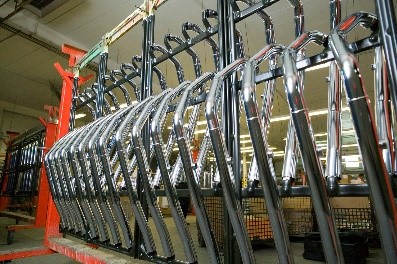
In this article, the focus is on rack electroplating, which encompasses various methods. However, before delving into the discussion, we review some practical concepts related to this topic.
Current Density: Current density refers to the amount of current entering a unit area, typically expressed in amperes per square decimeter (A/dm^2). As described by this parameter, as the area decreases, the current density value increases. In other words, in areas of the component with sharp edges, holes, or bends, localized increases in current density will be encountered. Each electroplating process has a specific range of current density, examples of which are presented in Table 1, and it should be noted that we should not exceed it when applying current to the component.
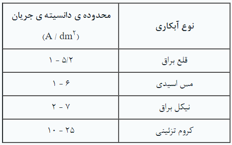
Current Efficiency: According to Faraday’s law of electrolysis, the electrochemical reaction occurring on the workpiece leading to the formation of the coating is directly proportional to the amount of electrical current passing through it. Current efficiency is defined using the following equation:
CE = ( Wact / Wtheo ) × 100
In this equation, CE represents the current efficiency, W_act is the mass deposited on the workpiece in practice, and W_theo is the theoretical mass predicted to be deposited on the workpiece based on Faraday’s law. The theoretical mass deposited based on Faraday’s law is obtained using the following equation:
Wtheo = I .t . M / n . F
Where the variables in this equation are: applied current density (I), plating time (t), molecular weight of the element (M), equivalent weight of the element (n), and Faraday’s constant (F). Due to side reactions such as hydrogen evolution, the cathodic current efficiency is always less than 100%. For example, in bright nickel plating, the cathodic current efficiency is around 98%, while in decorative chrome plating, this number ranges between 10 to 30%. The origin of these differences lies in the nature of the solutions and side reactions occurring on the workpiece.
Current Distribution: The distribution of current is determined by the geometry of the workpiece, including its protrusions, recesses, and the distance between the workpiece (cathode) and the anode. Regions with protrusions are referred to as high current density areas, while regions with recesses are called low current density areas. Since the thickness of the coating formed on the workpiece is directly related to the current density, achieving uniform coverage depends on how the current density is distributed across the workpiece.
The design of the workpiece holder should ensure that the difference in coating thickness between high and low current density areas is minimized as much as possible. Uniform current distribution is crucial for obtaining consistent and uniform coatings across the entire surface of the workpiece.
In electroplating, conditions must be prepared for all influential variables, including those mentioned, in such a way that ultimately, after undergoing the relevant processes, the piece possesses all the defined features from both a decorative and engineering perspective. In the rack electroplating method, three common approaches are utilized:
1- Wiring of the parts
2- Using jigs
3- Employing a combination of jigs and wiring
Furthermore, considering that the use of wiring method is still prevalent, a brief discussion on it is provided.
Wiring Method:
Generally, platers utilize their practical experience to employ cost-effective methods for moving the desired parts along the line. Among the most common methods used in plating workshops is the wiring method. While this technique may be effective for small and lightweight parts, it presents challenges when used for larger components. In this method, parts are individually or in small groups connected together using wire strands, typically made of copper, and moved along the line. Figure 3 illustrates an example of wired parts.
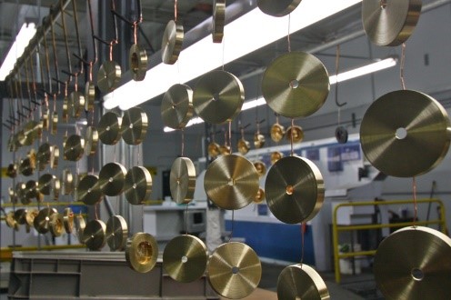
While the wiring method may initially appear convenient, it comes with its drawbacks, some of which are highlighted below:
1. Risk of wire breakage due to the weight of the part and its fall into the tank, potentially contaminating the solution and causing damage to the tank floor and other equipment.
2. Limitations in applying electrical current due to the thin cross-section of the copper wire, leading to overheating from excessive current flow, resulting in localized melting and wire breakage.
3. Restricted movement of the part and the possibility of collision with other parts and peripheral equipment inside the tank, such as heaters.
4. Contamination of solutions due to wire dissolution.
5. Generation of fine particles as a result of the plating of wires.
6. Costs associated with procuring wire and labor for opening and closing it.
7. Imprints left by the wire contact points on the parts.
Despite all the mentioned drawbacks, the wiring method is still used in plating units. However, considering the economic implications of these drawbacks, there will undoubtedly be a reconsideration of the use of this method.
The necessity of jigs:
When aiming to electroplate a piece using the hanging method, two factors must be considered:
A) Holding the piece in the solution and providing electrical conductivity to it.
B) Minimizing the impact of connection points on the piece and maximizing the coating efficiency.
A jig, also known as a fixture, template, or rack in some cases, is a tool that fulfills these requirements to the best possible extent. It’s one of the most crucial pieces of equipment that plays a pivotal role in increasing the production output of an electroplating unit. Jigs serve multiple functions, the most important of which are as follows:
1- Simultaneously moving multiple pieces along the line without them coming into contact with other parts.
2- Providing uniform electrical conductivity to the piece and creating consistent conditions for coating formation.
3- Increasing line efficiency by enabling the simultaneous handling of multiple pieces in manual and automatic lines.
4- Creating conditions for utilizing all the working spaces of the solution.
5- Providing a suitable platform for using peripheral equipment such as heaters, agitation systems, auxiliary anodes, etc.
6- Ensuring stable and uniform conditions in the final coating quality by maintaining the piece’s position throughout the processes (anode-cathode distance).
To meet the aforementioned requirements, the following considerations should be taken into account during the design and before the construction of jigs:
1- The type of electroplating process and the solutions with which the jig will come into contact.
2- The production volume and economic considerations related to it.
3- Matching the structure of the jig’s conductive body with the area of the piece to be plated.
4- Selecting suitable materials for constructing and coating the jigs to increase their service life.
5- The possibility of densely arranging pieces on the jigs to increase production efficiency while considering the nature of the plating solution.
6- The most suitable design for the prongs to ensure the stability of the piece on the jig while minimizing the impact points on the piece.
7- Ease of placing and removing pieces from the jig.
When designing jigs, the following factors should be considered:
1- Line Usage: In manual lines, the weight of the jig along with the pieces should not exceed 10 kilograms so that the operator can move it along the line easily. Additionally, the dimensions of the jig should be as compact as possible to prevent potential collisions with the tank or other equipment on the line. In automatic plating lines, the number of loaded pieces per cycle is much higher compared to manual lines. Therefore, jigs used in these lines, also known as flight bars, need to be stronger and ensure uniform electrical transmission to all pieces.
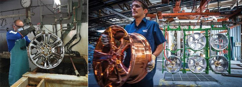
2- Rectifier Capacity: The required amperage to power all the pieces placed on the jig should be calculated and considered during jig design. Nowadays, with the use of appropriate software, the distribution of current density on the pieces can be predicted, and consequently, the number of pieces possible on each jig can be estimated.
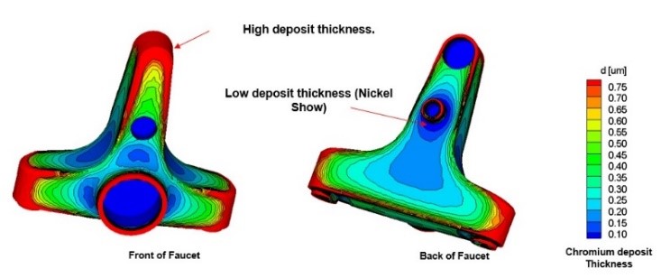
3- Tank Size: Plating tanks have defined working depths, and therefore, jig design should ensure that the pieces fit within this range. The working range of the tank varies depending on the type of process but usually starts about 10 centimeters below the solution surface and extends to about 10 centimeters above the tank floor. Proper jig dimensions prevent the construction of inefficient and disproportionate jigs. This aspect is more critical in automatic lines as they have more auxiliary equipment attached to the tanks.
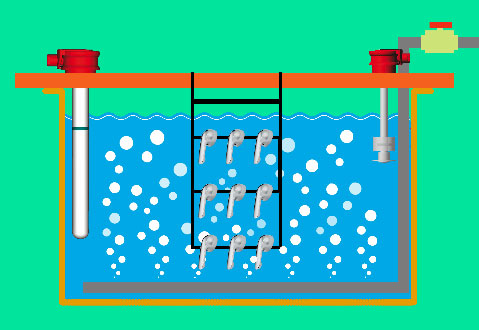
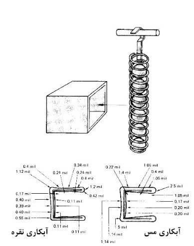
4- Plating Solution Type: Different arrangements on the jig should be considered depending on the behavior of the plating solutions. For example, in the case of chrome plating, it’s necessary to have fewer pieces on the jig with more spacing between them. This is different for solutions like silver plating due to their different behaviors and throwing power.
In Figure 7, a schematic comparison of the throwing power behavior of two types of cyanide plating solutions is illustrated. As observed, the thickness of the deposited coating formed under similar conditions for each of the solutions varies.
In Figure 8, a schematic representation of the main body of the jig along with some auxiliary parts is provided.
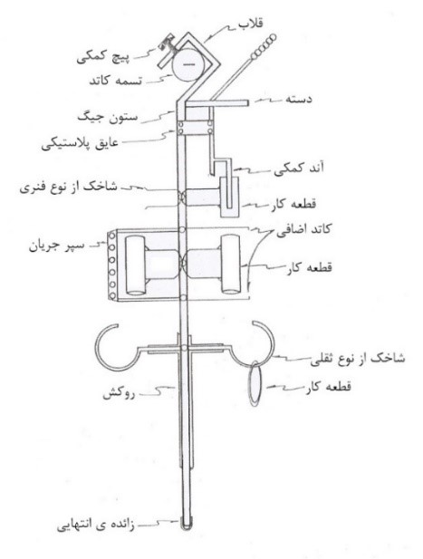
The main parts of the jig include the hook, column, branch, and auxiliary handle, which are ultimately coated with special materials. In addition to these components, in specific applications, other parts such as auxiliary anode, additional cathode, and current shield may also be utilized. Below, we’ll delve into the breakdown of some of the introduced parts in this schematic.
The jig hook: Since hooks play a crucial role in transferring electricity to the components, it’s essential for the hook to be designed in a way that ensures maximum connection between the jig and the cathode belt of the tank. Cathode belts are usually employed in two different cross-sections: round and rectangular. Figure 9 schematically illustrates how the jig hook is connected to these cross-sections. If there is a gap between the hook and the cathode belt, the electricity supplied by the rectifier may not be fully transferred to the components, resulting in a thinner coating than expected. In some cases, the line operator may increase the input electricity to overcome this phenomenon, but this increase, due to the improper contact between the hook and the cathode belt, can lead to localized temperature rise in this restricted area, and a significant portion of it dissipates as heat due to the resistance created. This temperature increase can have consequences such as melting and loss of coating.
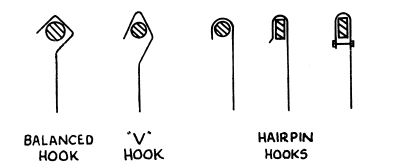
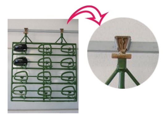
It’s worth mentioning that, for increased jig efficiency, hooks are usually made of copper. Additionally, in some cases, clamps or screws are used to ensure proper connection between the hook and the belt. Figure 10 provides images of these types of equipment and examples of their usage.

For automatic lines, different models can be utilized, as shown in Figure 11. These types of connections, due to the heavier weight of jigs in automatic lines, will provide a more complete connection since, due to their design, the hooks will be fully anchored onto the cathode belt by the weight of the jig.
The jig column: This part serves as the backbone of the jig, as it bears the weight of the components on one side and also conducts electricity to the components placed on the jig on the other side. Therefore, when selecting materials for making this part, materials should be chosen that not only have high strength but also have suitable electrical conductivity. Table 2 provides the amount of current passing through various sections of some materials used in making jig columns. It is essential to note that when selecting copper sections for purposes such as tank belt tensioning or making hook and jig columns, the compatibility of the copper section and the amount of current passing through it should be considered.

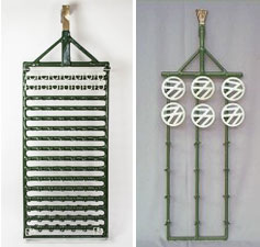
As observed, copper has the highest conductivity among metals and can be the best option. However, it has been observed that most platers, due to the reduction in costs associated with procuring jigs, choose iron options when ordering. Perhaps this perception arises because, in the initial comparison, the price of iron is much lower than copper, seemingly saving costs in jig construction. However, due to the significantly lower conductivity of iron, there will be much more electrical loss, resulting in the heating of the jig body and localized melting of the coating. The use of bronze is suggested as a better option, although it still has less conductivity compared to copper. Figure 12 shows images of various jigs with different types of columns.
Jigs and Fixtures: In the design and construction of jigs and fixtures, several parameters need to be considered, with the most important ones being:
1. Sensitivity of which part of the component during the machining process.
2. Where on the component, the impact points of the jigs will be permissible.
3. Materials to be used in making the jigs.
Among these, other indicators such as preventing part collision with the jig, distance of parts to the anode, drainage of solutions from within the parts, reducing the likelihood of solution migration, and also how to distribute current density on the part should be considered in the design. It should be noted here that material loss is not only about solution runoff from the parts during their movement along the line, but also if the distribution of coating thickness on the part is uneven and non-uniform, meaning there is a significant difference in thickness of the coating at different points of the part, it itself constitutes material loss. This is because the coating is thicker at some points while at other points it has not reached the desired thickness, and as a result, the coating has not been formed satisfactorily at all points of the part.
Common jigs are generally categorized into two types: gravity and spring-loaded.
1. Gravity Jigs: In this method, the part is suspended on the jig, and as shown in the schematic (Figure 8), its design should be such that when the jig moves along the line, the parts do not detach from it. Figure 13 illustrates an example of a jig with this type of jig.

سهولت در گذاشتن و برداشتن قطعات از عمده ویژگی های این نوع شاخک ها می باشد. بدیهی است که استفاده از این روش برای قطعاتی که دارای سوراخ هستند پیشنهاد می شود.
2. Spring-loaded Jigs: This type of jig itself comes in two forms. The first type is when all the jigs involved with the part are movable and spring-loaded, and the second type is when one or more jigs are fixed. The second type is more common in the electroplating of plastic parts. Figure 14 shows an example of this type of jig.
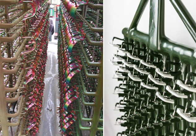
In cases where there is mechanical or air turbulence in the solution, the use of spring-loaded jigs is recommended because there will be less likelihood of parts shifting. Some types of these jigs are shown in Figure 15.
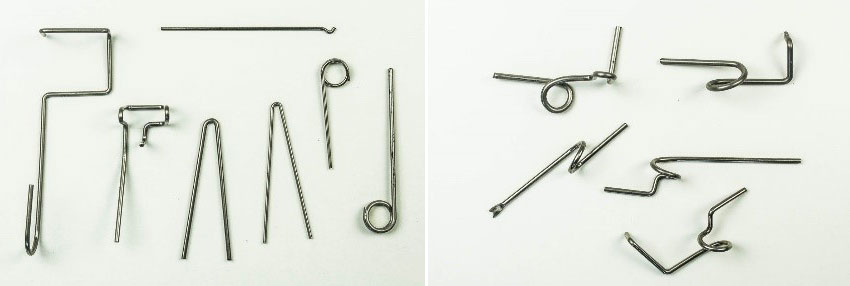
Each of these jigs will be used depending on the geometry of the part. Typically, stainless steel is used in the construction of these types of jigs. In general, using stainless steel in jig construction provides conditions for their dehydration and reuse. Figure 16 shows images of some parts placed on jigs.
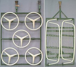
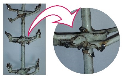
Jig Coating: Since during the plating line, a variety of chemical solutions with different pH ranges exist, the jig used must be protected against chemical reactions resulting from contact with these solutions. Hence, special coatings are used to prevent undesired reactions between the jig and the solution. These coatings, usually made of PVC-based plastisols, must be continuously and void of any holes applied to the surface of the jig body using a dip-coating method. It’s worth noting that since jigs are constantly loaded and unloaded throughout the day and are subjected to fatigue loading (fatigue loading refers to applying force to a part over a specific period), the coatings applied to the jig body must have suitable resilience properties. Additionally, jig coatings must be resistant to thermal shock. The importance of this issue lies in the fact that during the plating line and depending on the type of plating process, the solutions used have various temperature ranges, and in some cases, temperature differences of up to 60 degrees Celsius can occur. If the coating applied to the jig lacks these features, it will develop cracks after a short period of time. These cracks can lead to problems such as solution migration along the line, dissolution of the jig body due to contact with the solutions, contamination, and material loss due to the plating of the jig body. Figure 17 shows an image of a cracked coating sample.
It is worth mentioning here that for some processes such as anodizing or electropolishing, which often use titanium jigs, coating the jigs is not common due to the resistance of the jig body to the solutions. However, if no coating is used and electricity is applied, a significant portion of the applied current will be lost through the jig body. Therefore, it is recommended to use coated jigs as much as possible.
Jig Handling Assist: To facilitate the operator in transferring jigs into tanks, it is recommended to incorporate handles onto the jigs. An example of a jig with a handle is shown in Figure 18.
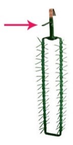
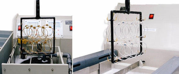
Combination of Jigs and Wire: In some cases, depending on the type of parts and their sensitivity, a combination of wire and jigs can be used to transfer parts in the plating line. In this method, the main frame is provided by the jig, and then, using wire, which can vary from one to several rows, areas for placing the parts are created. This method is used in plating plastic parts as well as precious metal plating. Figure 19 shows an image of this type of jig.
Auxiliary Equipment for Improving Jig Performance:
As mentioned, the use of jigs has many advantages, including providing the possibility of employing auxiliary equipment during the plating of specific parts. Among these equipment, auxiliary anodes, additional cathodes, and current shields can be mentioned, which are necessary when plating parts with geometric complexity. Below is a brief overview of the application of these items and how they are utilized. It’s worth noting that all mentioned devices are aimed at controlling and modifying the distribution of current on the parts.
Auxiliary Anode: In cases where internal parts of the component need to undergo the plating process to enhance the solution’s throwing power in these areas, auxiliary anodes are used. In this regard, jigs provide the capability to maintain the position of the auxiliary anode relative to the part. It is obvious that when using auxiliary anodes, an insulating material is used to prevent cathode-anode connection. Figure 20 illustrates an example of employing an auxiliary anode on jigs.

Additional Cathodes and Current Shield: As mentioned in previous sections, current concentration in certain areas of the part, such as edges, is higher compared to other areas, leading to changes in coating properties, including thickness distribution. Therefore, to mitigate current concentration in these areas, two methods are utilized.
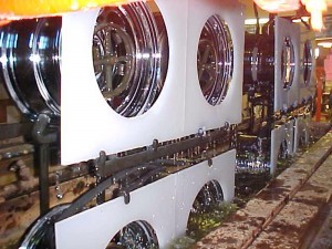
In the first method, an additional cathode is placed near areas with high current density to absorb a portion of the applied current, thereby preventing an increase in current magnitude. In the second method, an insulating material, serving as a current shield, is placed between the part and the anode. This technique prevents direct exposure of areas prone to increased current density, such as part edges, to the anode. In both methods, jigs facilitate the deployment of these auxiliary equipment alongside the part. Figure 21 shows an example of current shield placement on a jig in front of the part.
In some cases, and depending on the type and quantity of parts, special jig designs may be used. One of these methods is cathode rotation, which will be discussed further below.
Rotating Cathode: In typical plating tanks, jigs are designed for two-sided work. Figure 22 schematically shows the placement points of the part in this configuration.

However, if the jig hook is given rotational movement by a motor, the placement positions of the part on the jig will at least triple in size, depending on its size. Figure 23 schematically illustrates possible positions when the jig is rotating.

This method, based on rotating the jig, is called the rotating cathode method. This method is highly effective in increasing plating efficiency. Additionally, due to the rotation of the parts during the process, the coating thickness distribution on the part will be more uniform, and plating of areas with more complex geometry will be possible. Practical examples of rotating jigs are shown in Figure 24. It is worth mentioning that some jig manufacturers apply this method separately for each of the parts. These jigs enable the rotation of the part to ensure complete solution drainage from the internal parts of the components after the jig exits the solution and is positioned above the tank.

Summary:
In this article, an attempt has been made to briefly present some basic concepts that should be considered when using jigs. Considering the influential role of jigs in determining the efficiency of a plating unit, it is recommended that before construction, all aspects related to coating quality and production volume be taken into account. The use of efficient materials in jig construction, considering relevant economic considerations, is strongly advised. It is necessary to mention here that although all governing standards in jig design and construction may not be implemented by manufacturers, platers should pay attention to these points when ordering. In other words, as platers’ awareness of the equipment used in workshops increases, the quality level of products related to this field, such as tanks, rectifiers, jigs, chemicals, etc., will undoubtedly improve, and as a result, manufacturers will offer higher-quality products. In fact, the demand for quality equipment will lead to the cessation of production of inefficient products.


