


Research articles
The importance of employing standard and efficient equipment in improving the quality and efficiency of the plating process
Part 1: Turbulence
Reza Mehtar Ghorehdaghi (MSc in Corrosion and Materials Protection)
Peyman Samadi (MSc in Materials Engineering and Metallurgy)
Abstract:
The nature of the electroplating process dictates that for achieving components with the highest quality coating and consistent qualitative results, the variables governing the process should be uniform across all points and conditions. Considering that the utilization of agitation is the most effective method in establishing ideal conditions for the most influential parameters in the electroplating process, such as chemical concentration and temperature, while suspending impurity particles in the solution enhances filter efficiency and eliminates the presence of these particles from the solution, various agitation systems are examined in this article.
Introduction:
During the 19th century, when the electroplating process was discovered and industrialized, the basic physics and chemistry governing it were superficially understood, and the primary concern of industrialists was finding efficient methods for dissolving metals intended for electroplating. However, over time, advancements were made; chemically, new dissolution methods and the creation of solutions with higher metal ion concentrations, pH control of the solution, and accelerating anode dissolution were developed. From a physical standpoint, solutions’ temperature elevation, agitation to prevent stagnation, and dispersion of gas bubbles formed during the electroplating process were proposed. Since the inception of agitation until today, its purpose, originally aimed at preventing solution stagnation, has expanded to other objectives such as increasing plating speed and improving the quality of deposits on the component. Consequently, the method of agitation has evolved over time. Initially, during the early stages of electroplating, agitation was not achieved using electric motors as they were not yet invented at that time. Hence, it was mechanically carried out using human force. However, since the industrial production of electric motors (approximately from the latter half of the 19th century), methods of solution agitation took on different forms, and various systems such as moving the cathode belt back and forth were invented. Over time, with the expansion of scientific knowledge and the experience of electroplaters, newer forms of agitation methods emerged, and in some cases, previous methods were improved upon.
Today, agitation is recognized as a vital factor in electroplating processes, with several important reasons for its use:
1- Prevention of solution stagnation and dispersion of materials and reactants, as well as avoiding solution stratification, which results from concentration gradients. This phenomenon, known as concentration gradient, occurs due to the decrease in metal ion concentration in the solution adjacent to the cathode surface. If this decrease is not compensated, the rate of coating growth will decrease.
2- Increasing deposition rate by reducing the diffusion layer, which accelerates the diffusion of metal ions from the solution to the surface of the component.
3- Reducing the heat generated at the electrode/electrolyte interface. For example, in the anodizing process, the anodic film acts as a heat barrier, resulting in an increase in the component’s temperature during the process. Agitation plays a significant role in this regard.
4- Assisting in the incorporation of secondary particles into the coating in composite electroplating processes.
5- Optimizing or controlling the mechanical properties of the deposit, including grain size, internal stress, hardness, and other indicators such as throwing power and metal distribution. The effect of agitation can be directly examined by measuring the thickness of the diffusion layer, but unfortunately, this method is very challenging. Therefore, other indicators are evaluated, with the most common being the measurement of current density to achieve the desired coating in terms of brightness/roughness/hardness.
6- Removing hydrogen films formed on the component’s surface and preventing embrittlement and porosity in the coating.
7- Increasing the efficiency of anode dissolution.
Agitation in the solution should be considered from two perspectives: on one hand, overall agitation of the solution, and on the other hand, agitation specifically at the interface between the component and the solution. General agitation relates to the total volume of the solution, especially in cases where we aim to ensure uniformity of the solution, dispersion of gases, and mixing of secondary particles in composite electroplating. Mechanical agitation and air agitation are among the most common methods in this regard.
On the other hand, creating agitation at the interface between the component and the solution accelerates the electroplating process by reducing the thickness of the diffusion layer formed in front of the component. This type of agitation accelerates the transfer of reaction agents to the component surface and affects the products of anodic and cathodic reactions. In this context, moving the cathode can play an effective role.
Today, the main and most common methods of creating agitation in electroplating solutions include:
1- Mechanical agitation: Movement of the cathode (gearbox-driven), rotating cathode, vibrating the workpiece, using impellers and paddles, and barrel rotation.
2- Using ultrasonic waves.
3- Natural displacement of the solution.
4- Air agitation.
6- Creating turbulence in the solution: pumps and eductors.
Assuming that the stagnant solution has an agitation index of 1, the improvement factor for each of the above methods is provided in Table 1.
Table 1. Electroplating Process Improvement Factors
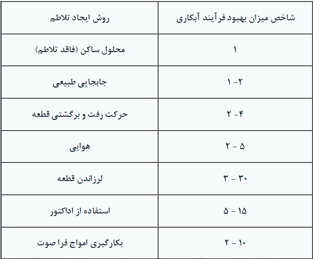
It is reminded that these numbers are relative and various numbers have been reported in different sources, but their effectiveness remains consistent. Below, each of the methods for creating agitation in the electroplating solution is discussed.
1-Mechanical Agitation
1-1Cathode Movement (Gear-driven):
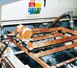
In this method, the cathode belt is connected to a gearbox, causing the workpiece to move back and forth within the solution. This intermittent movement ensures the periodic replacement of the cathode surface film and the removal of hydrogen bubbles formed on the workpiece. Figure 1 illustrates an example of a tank equipped with a gear-driven agitation system. The appropriate speed of movement largely depends on the size and geometry of the components. In this type of agitation, any excessive increase in the speed of the components should be avoided, as it may lead to the workpiece (jig) hitting the cathode belt, ultimately causing the workpiece to collide with its neighboring jig and resulting in scratches and marks on the components. Furthermore, this phenomenon may lead to the interruption and reconnection of the electroplating current. Typically, when optimal speeds do not achieve the desired impact on the electroplating process, air agitation is simultaneously employed.
In some cases where there are limitations regarding the internal space of the tank, especially in cleaning processes and alkaline solutions, the agitation system mentioned is optimized to move the workpiece up and down within the tank. Generally, to achieve the best results, manufacturers of such agitation systems must consider the following:
Motor: The power of the motors used varies and is selected according to the length of the tank and the weight of the components. It should be noted that excessive motor power can cause jigs to hit or move on the cathode. Due to the proximity of the motors to corrosive solutions, resistance to corrosion is an important factor in motor selection. Vertical motors are used in workshops with space constraints. Additionally, in cases where multiple tanks are aligned, a single gearbox-driven agitation system can be used, allowing the workpiece to be moved horizontally or vertically. It is worth mentioning that this type of system is common in fully automatic electroplating lines and is extensively used in China, where high production rates are always significant.
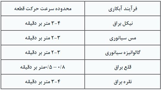
Reducer Gear: The purpose of these gears is to adjust the required revolutions per minute and match the motor output with the speed of the workpiece. These components must always be submerged in oil and periodically inspected to prevent dry operation, which can lead to tooth wear and subsequently disrupt the movement of the components. The use of suitable materials in the construction of reducer gears can significantly increase their lifespan. For example, Figure 2 shows an example of using PVC materials in the construction of reducer gears.
Range of Motion for Components: The speed of movement for components varies depending on the type of electroplating process, but generally, it is recommended to avoid high speeds when moving components within the solution. Table 2 shows the speed of movement for components in some electroplating processes.
Table 2. Movement Speed of Parts in Agitation Gearbox
It is reminded that in some cases, the movement of the component may have two states. For example, in the process of nickel plating, manufacturers often recommend two-dimensional agitation to achieve a more uniform coverage.
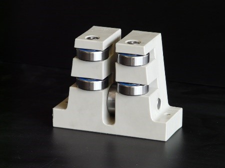
Racking: The most common problem with racks is their tendency to become stuck, which results from the intermittent splashing of the solution onto them. Therefore, sponge racks are preferred. It is worth noting that using oil for lubricating the movement of racks is not recommended as it can contaminate the electroplating solutions. The use of protective covers to increase the lifespan of racks can be practical. Various designs are used to improve the performance of racks, an example of which is shown in Figure 3.
2-1Rotating Cathode:
This type of system is typically employed when relatively large parts with low volume are desired, and when the highest deposition rate is required, such as in the electroforming process. Here, the part is connected to an electromotor system and rotated during the electroplating process. Examples of this method include the production of mold plates and combustion engine nozzles.
In the first example, the cathode plate is positioned horizontally, 8 to 15 centimeters away from the anode, and fully immersed in the solution while rotating at a speed of 100 to 150 revolutions per minute, depending on the process type, which can vary. In the case of copper electroplating, thicknesses approaching 500 microns per hour can be achieved. Typically, due to the high deposition rate in electroplating, peripheral equipment such as shields is used to control the coating thickness.
It is worth mentioning that nowadays, this method is also prevalent in electroplating small parts such as sanitary fittings, jewelry, handles, and door plaques. This allows the part to be uniformly exposed to anodes in different angles and recesses, ensuring a uniform coating is formed on them.
3-1Vibration:
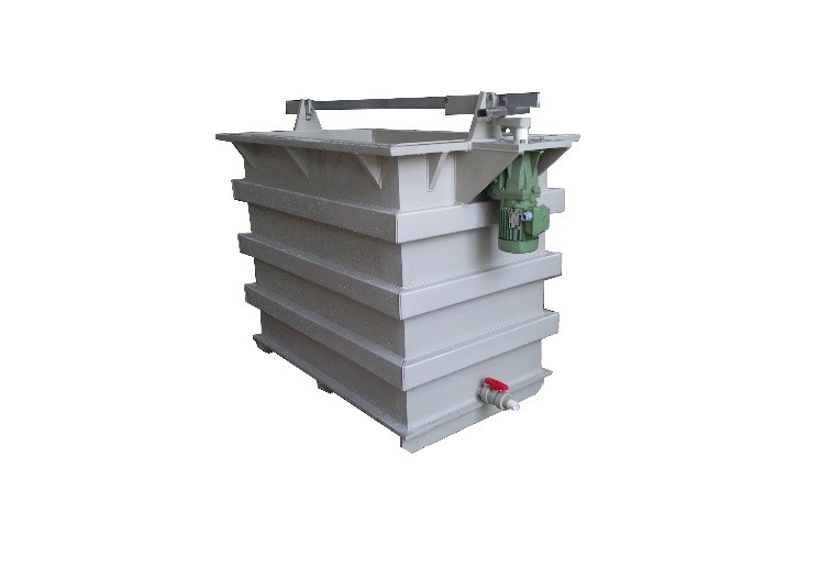
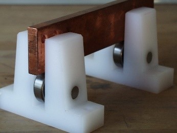
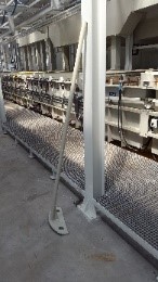
This method is based on vibrating the workpiece. The parts placed on the belts are moved with a specific range of motion during the process. This operation causes gas bubbles formed on the surface of the workpiece to disperse, and at the same time, eliminates the concentration gradient near the workpiece, accelerating the deposition process. Figure 4 shows an example of tanks equipped with a vibrating system. The primary application of this system is in electroplating printed circuit boards.
It is worth mentioning that the positioning of vibrators, often located near the surface of the solutions, exposes the components of these devices to corrosive vapors. This phenomenon ultimately leads to fatigue crack formation. Additionally, in some cases, the desired parts may be very heavy, imposing high pressure on the device and causing the motor to overheat. Therefore, key features of a suitable vibrator include the use of proper coatings to protect against corrosion, employing effective insulating materials to prevent corrosive agents from entering the device, using oils that perform well at high temperatures, and covering the wire coils with insulating materials to increase reliability and device lifespan.
4-1Using Propeller and Paddle:
Today, these equipments are rarely used, and the main reasons for that are:
A. Propellers and paddles cannot create uniform agitation throughout the tank.
B. When dealing with large plating units and considering the use of this type of system, the costs are significantly higher compared to other methods.
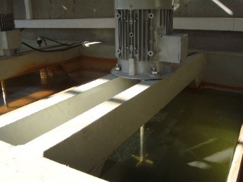
Despite these drawbacks, in some cases, such as initial solution preparation or creating partial agitation in wastewater neutralization systems, this method can still be utilized. Figure 5 shows a system for creating agitation using an electric motor equipped with a propeller and an example of a paddle made of polypropylene.
5-1Barrel Rotation:
Although barrel plating may not initially appear to be aimed at creating agitation in the solution, its nature is such that it introduces intense agitation into the solution. Depending on the speed of rotation and the volume of the barrel, the intensity of the agitation created can vary. Proper angles in the design and construction of barrels can significantly contribute to improving the efficiency of the plating process for components. This is achieved by ensuring proper circulation of the solution in the tank on one hand and guaranteeing the arrival of fresh solution to the components inside the chamber on the other hand.
2-Utilizing Ultrasonic Waves:
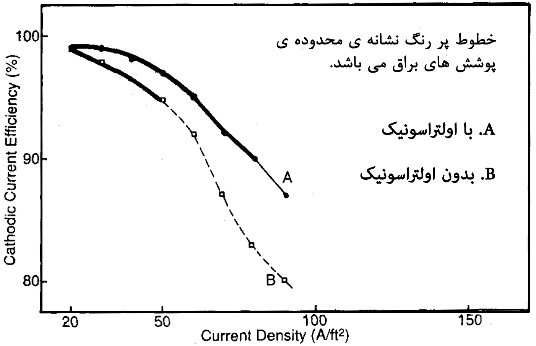
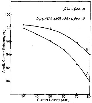
In recent years, the use of ultrasonic waves has expanded significantly due to its physical properties. In this type of agitation, ultrasonic waves, typically with frequencies above 16 kHz, are introduced into the solution using transducers. This process intermittently creates areas with variable pressures on the surface of the components. These pressures range from 200 atm and higher. The mentioned pressures cause the formation of turbulent flows on a micrometer scale, trapping very small air bubbles at the interface between the component and the solution. Eventually, these very fine bubbles act as nucleation centers for larger bubbles. These bubbles then grow and dissipate at the highest possible intensity (almost at 1000 atm pressure), creating intense agitation on a micronic scale. Using this method, agitation much more intense than mechanical agitation (gear-driven) is created. This agitation significantly alters the hydrodynamic conditions governing the interface between the component and the solution, leading to a reduction in the thickness of the diffusion layer against the component. Consequently, the concentration gradient in front of the component becomes uneven, increasing mass transfer from the solution to the adjacent areas of the component. This translates into an increase in the availability of ions for electrochemical reactions on the surface of the component. Diagrams illustrating the effect of employing ultrasonic waves on the efficiency of cathodic and anodic currents are shown in Figure 6.
The importance of agitation using ultrasonic waves in electroplating processes lies in its ability to influence parameters such as polarization aspects, mass transfer, and the surface condition of the electrode. Additionally, this type of agitation affects the formation of hydrogen, which occurs simultaneously with the metal deposition process.
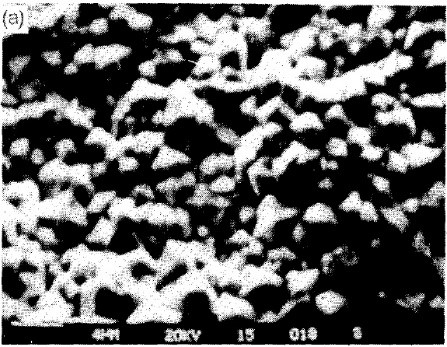
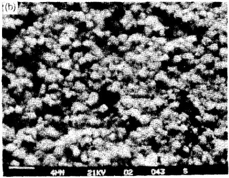
In stationary tanks, some of the produced hydrogen enters the coating, causing embrittlement, while the rest disperses onto the surface of the component (cathode), resulting in the formation of streaks, pits, etc., on the coating. By utilizing ultrasonic agitation, the hydrogen film quickly separates from the component’s surface, resulting in a smoother coating. SEM images in Figure 7 illustrate the effect of employing ultrasonic waves on the nickel coating resulting from the electroplating process. As observed, the nickel coating structure shows greater compactness when ultrasonic waves are used.
The significant impact of ultrasonic waves has led to their recognition as an efficient option in the preparation and electroplating of geometrically complex parts. For example, in the electroplating of valves, especially gate valves, which are directly cast and often contain significant amounts of casting materials trapped inside, conventional preparation methods fail to remove contaminants from within the component. As a result, these materials remain with the component throughout the electroplating process and ultimately lead to various defects in the main plating tanks. In such cases, the use of ultrasonic waves can effectively remove these particles from inside the component.
The importance of this method lies in its high precision, reduction of preparation times, and consequently, increased line efficiency. Perhaps the only drawback of this method is its high implementation cost compared to other methods.
3-Natural Convection of Solution:
A method for creating gentle agitation in situations where none of the other agitation systems are available. On the other hand, this system is recommended for maintaining the uniform temperature of the solution even when other agitation methods are used. This method is especially suitable for barrel plating. In the general structure of this method, a support plate is used against the hot or cold water coils placed inside the tank. This plate has space above and below the tank, creating a confined space for the coil. When the coil generates heat, the solution in the adjacent space rises due to the phenomenon of buoyancy and enters the main part of the tank. Also, due to the phenomenon of solution displacement, the cold solution present in the main space of the tank is transferred to the compartment opposite the coil. With this process, the rotation of the solution will be constant throughout the process
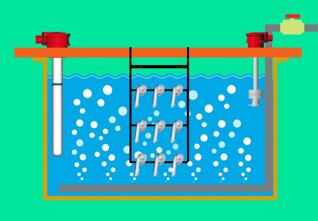
4-Air Agitation:
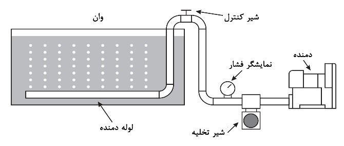
In this method, compressed air is delivered into the solution through pipes installed at the bottom of the tank, equipped with multiple holes at specific angles, using a compressor or blower. This air agitation causes turbulence in the solution. Figure 8 schematically illustrates this method.
Some of the suitable features of compressors and blowers include:
1. Generating clean air free from any oil and other contaminants.
2. Producing minimal noise pollution in the workshop environment.
3. Having low maintenance and repair costs.
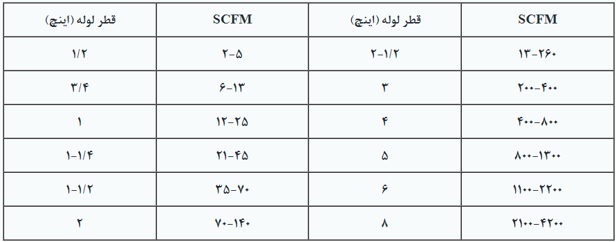
The piping system plays a crucial role in the efficiency of the air agitation. The diameter of the pipes depends on the amount of Standard Cubic Feet per Minute (SCFM) of air required to be delivered into the tank every minute. Pipes with very small diameters cause additional friction and reduce the efficiency of the agitation. Table 3 provides the minimum and maximum air flow rates through pipes of various sizes.
Table 3. Correlation between Saez’s Lullaby Scale and Huawei’s Exit Scale
Among these, various designs are used for air piping in tanks, with the most common form depicted in Figure 9. As observed, the number of air diffuser pipes varies and depends on parameters such as tank dimensions, the type of electroplating process, and the type of part being electroplated.
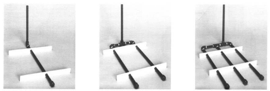
Typically, the “effective agitation zone” resulting from each pipe covers a range of approximately 15 to 23 centimeters.
Among these, there are rules in the design of the piping system, the most important of which are as follows:
Rule 1: The total area of the holes created on the pipes for each SCFM should be approximately 1 square inch per 5.62 SCFM.
Rule 2: The optimal diameter size for the holes is approximately 0.2 inches, which corresponds to a hole area of 0.04 square inches. Therefore, to achieve a total hole area of 1 square inch (approximately 645 square millimeters), we will need 144 holes.
Rule 3: It is always recommended that if holes of various diameters are to be created on the pipes, the area of each hole should be calculated separately, and ultimately, the number of holes required to achieve the total area should be estimated.
Figure 10 provides a schematic of the air piping layout.
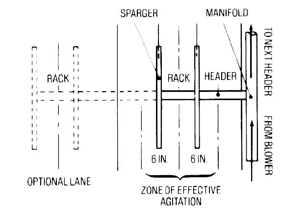
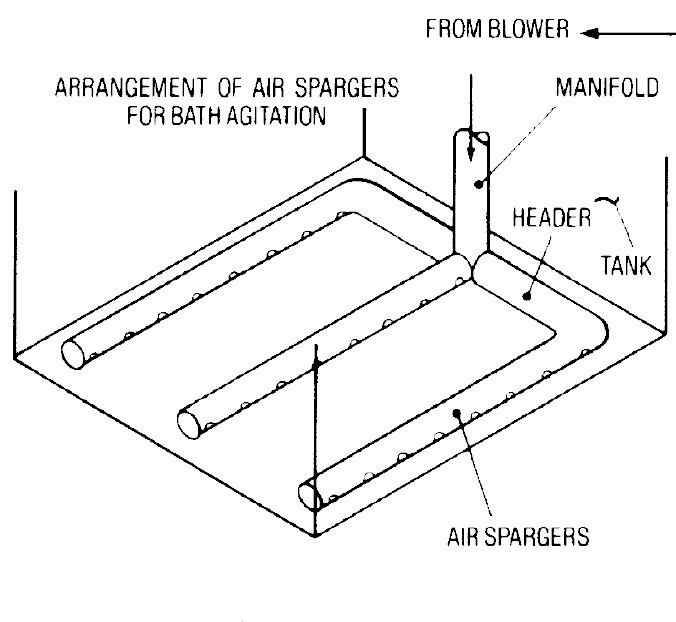
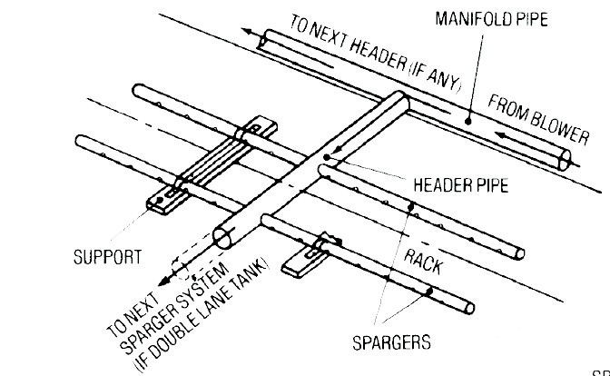
Figure 10. Schematic of an Air Piping System.
In calculating the desired air agitation, depending on the volume of the tank and considering the governing equations, we will arrive at the effective air volume. The practical equations for calculating the pressure and the required air are as follows:
The pressure calculation equation is expressed as:
P=0.43×T×D+0.75
In this relationship, T is the depth of the solution in feet, D is the specific weight of the solution
The relationship to calculate the amount of flow required in terms of SCFM is:
Q=AF
In this equation, A represents the total area of the tank in square feet, and F represents the turbulence factor in terms of ft2/SCFM.
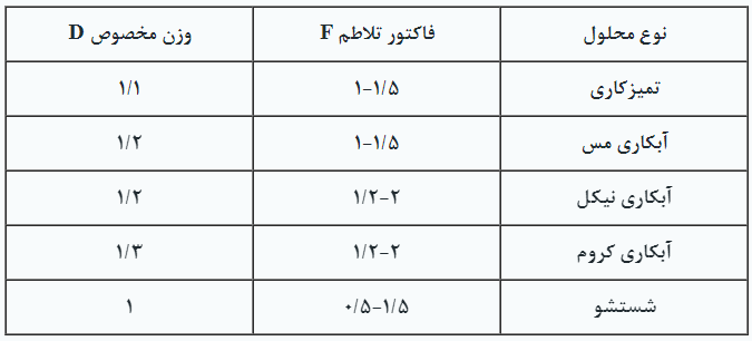
Table 4. Numerical Values for Turbulence Factor and Specific Weight in Some Plating Solutions
Table 4. Numerical Values of Agitation Factor and Specific Gravity in Some Electroplating Solutions
Sure! Due to the widespread occurrence of this type of turbulence in various electroplating processes, an example of how to calculate the required turbulence level is presented below.
Example: Two copper acid plating baths require air agitation. The dimensions of the tanks are identical and are as follows: 120×90×180 cm³ with a solution depth of 107 centimeters. To calculate, we proceed as follows:
First, we calculate the pressure according to the formula P=0.43TD+0.75:
P=0.43×3.5×1.2+0.75=2.6 PSIG
Next, we calculate the required flow rate inside the tank:
Q=AF=2 Tanks×3×6×1.5=54.0 SCFM
The turbulence factor is extracted from the provided table, which is 1.1 for the copper bath. After obtaining the numbers, we refer to the pump output power tables and select the appropriate type.
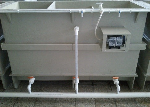
It’s worth mentioning that employing air agitation in plating tanks can significantly impact their efficiency. This is particularly noticeable in cases where the desired geometrical complexity of parts is involved. Consequently, it allows for shorter plating times, translating to increased production efficiency. Figure 11 illustrates an example of a plating tank equipped with an air agitation system (blower).
Air agitation, despite its relative popularity among platers due to its cost-effectiveness, comes with some accompanying challenges. The most significant of these are:
1- Closure of air outlet holes in the air pipes due to their small diameter, resulting in uneven agitation. This can lead to stagnant solution in some parts of the tank, especially in acidic copper solutions.
2- Introduction of air into the solution often results in foam formation at the solution surface and increases the risk of toxic vapor release.
3- Increased heat loss rates due to the movement of air bubbles from the bottom of the tank to the solution surface, leading to higher energy consumption and costs.
4- Oxidation and decomposition of some additives due to air ingress.
5- High maintenance costs of air agitation equipment and the possibility of oil contamination in plating baths.
6- Creation of excessive noise during operation.
7- Possibility of increased roughness of the coating due to the suspension of impurity particles.
Many of the above issues can be addressed through periodic inspections and the use of auxiliary equipment. For example, to reduce heat loss, using polyethylene balls can be an effective solution.
5. Creating Turbulent Flow in the Solution:
5-1Pump:
Creating turbulent flows within solutions is one of the newest and most effective methods of agitation, which has a significant impact on plating parameters. This is applied in plating lines using an executive pump, where the solution is removed from a specific point in the tank during the process and re-enters from another point. Essentially, the pump functions like the heart in the human body, circulating the solution throughout the tank. When selecting a pump, the following factors must be considered:
-Plating solutions cover a wide range of pH levels.
-The warmth of the solutions can cause cavitation, reducing pump efficiency and leading to extra noise, impeller wear, and damage to pump insulation.
-Cooling of the solutions can result in the formation of crystalline salts, hindering pump performance.
-Solutions have varying densities that affect pump power during temperature changes.
-Pumps operate in environments that lack ventilation, necessitating the selection of an appropriate enclosure.
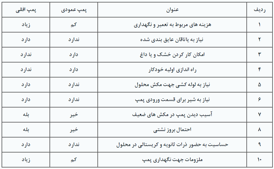
Pumps are available in both vertical and horizontal configurations, as depicted in Figure 12. Additionally, the advantages and disadvantages of each are outlined in Table 5.
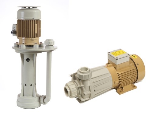
Table 5. Comparison of Vertical and Horizontal Pumps
Horizontal pumps are further categorized based on their impeller-driving mechanism into mechanical and magnetic types. In the mechanical type, the impeller is directly connected to the motor shaft and rotates accordingly. In these pumps, it’s essential to insulate all parts in contact with the solution, including the shaft. The mechanical seal component in these pumps is constantly exposed to potential damage. In the magnetic type, the pump is coupled with a pair of magnetized iron parts, causing the magnetic impeller to rotate due to the induced field from the iron parts. These are commonly referred to as magnetic pumps. They are much more efficient as they do not require direct contact between the impeller and the motor, thus eliminating the need for insulation. Schematics of these pumps are provided in Figures 13 and 14.
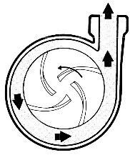
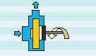
Figure 13. Schematic of Mechanical Pumps
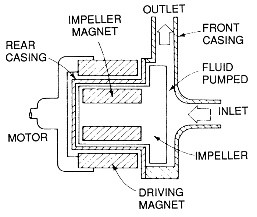
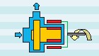
Figure 14. Schematic of Magnetic Pumps
When selecting power and evaluating pump performance, the following factors should be considered:
-Required flow rate.
-Installation position of the filter.
Distance and diameter of the outlet pipe.
Calculating Pressure Drop
Corrosiveness of the Solution as Electroplating solutions cover a wide pH
Solution operating temperature.
Depending on the type of process, the number of turnovers per hour varies. For most plating and washing baths, 5 to 15 turnovers per hour will create adequate agitation. However, for copper and nickel plating baths, this number may reach 30 turnovers or more. In cleaning baths, a minimum of 10 turnovers per hour is recommended, and in cases where contamination levels are high, 20 turnovers per hour are typically advised.
During the installation of pumps, observing the following points can significantly help increase their efficiency:
-Choose the shortest possible suction pipe length and, if possible, use a suitable hose (flexible) with spring reinforcement.
Avoid the use of elbows, bends, and fittings in the suction section of the piping system as much as possible.
When the use of non-return fittings is necessary, preferably install them at a distance of ten times the diameter of the pipe used compared to the pump inlet.
The suction pipe and the solution inlet to the pump should be placed at opposite points in the tank and, if possible, at a distance from each other.
Ensure that the solution level is sufficient to prevent air from being drawn into the pipe.
Reinforce the piping system near the pump to prevent any stress on it.
Ensure there are no leaks in the piping system.
Increase the pipe diameter by at least one diameter for cases where the pump is far from the tank or when the solution temperature is high.
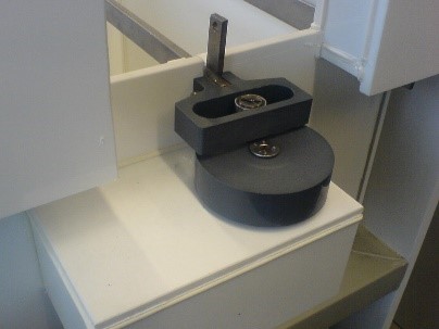
5-2Edactor
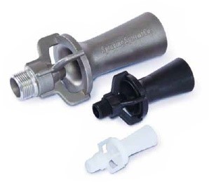
The eductor system operates based on the Venturi effect, whereby a high-pressure, high-velocity, low-flow solution is converted into a low-pressure, low-velocity, high-flow solution. Eductors are used at the outlet of pumps to change their output flow rate. In other words, by altering the outlet sections of the solution, the output volume can be increased. Figure 15 depicts images of an eductor. Referring to the “Plating Process Improvement Factor” table presented at the beginning of the article, it can be observed that agitation by this method is one of the most effective techniques, although its success largely depends on the design and implementation method.
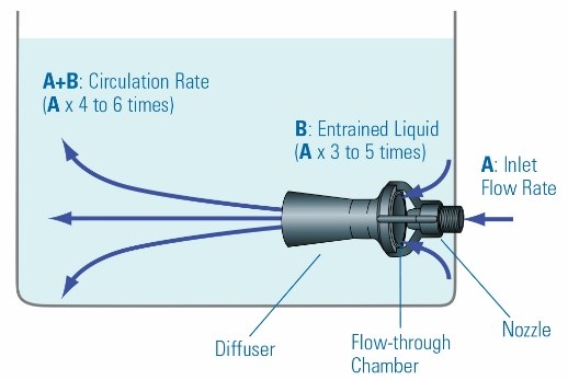
The working principle of the eductor is illustrated in Figure 16. As shown, the velocity of the outlet solution can be increased up to 6 times the input flow (A).
To increase the efficiency of this system, it’s necessary to correctly determine its application. Generally, the use of eductors serves three main purposes:
A. To create intense agitation in plating baths and move the solution towards the parts to be plated.
B. In electroless nickel, electroless copper, and alkaline zinc plating baths where the solution should not flow directly towards the parts.
C. In plating processes accompanied by significant deposition of residues, such as degreasing and phosphate coating, to move the solution towards the bottom of the tank to prevent sedimentation of residues and aid in their separation by filtration.
Based on information such as the depth of the solution and the type of process, variables such as pump pressure and the number and size of eductors can be calculated. In most cases, it’s better to install a valve between the pump and nozzles to adjust the required agitation level. It’s crucial to use pipes that are proportionate to the size of the pump outlet to prevent pressure drop. Figure 17 illustrates schematics of some designs of agitation systems using eductors in various processes.
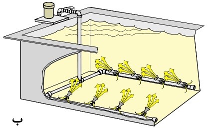
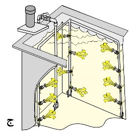
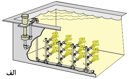
Figure 17. Schematic of Tanks Equipped with Agitation System by Adaptors:
– For Plating Printed Circuit Boards and Suspended Parts
B. For cleaning parts inside baskets and in a hanging position.
C. For mixing raw materials in the solution.
There are many practical examples of using eductors, and here is one of them. In a plating workshop with a relatively large cleaning section, to remove contamination and rust from parts, initially, an air agitation system was used. In this method, to ensure the cleanliness of the parts, the cleaning operation was repeated 4 to 5 times to completely remove the oxide layer from the parts. One of the problems with this method was the clogging of air agitation system’s nozzles and ultimately, uneven agitation in the solution. The use of eductor agitation solved the nozzle clogging issue initially and resulted in up to 74% savings in material consumption. The reduction in material consumption was due to the elimination of oxidation caused by air presence in the solution and reduced losses due to evaporation. Finally, an 11% reduction in overall costs was reported because the cost of air production had also decreased. Here are some processes where the eductor agitation system has been successful, significantly increasing efficiency compared to other agitation methods: degreasing and rinsing, decorative acid copper plating, printed circuit boards, phosphate coating, gold/silver/rhodium/cadmium and lead plating, electroforming, nickel and chromium plating, anodizing, electroless nickel and copper plating.
In general, the most significant impacts of the eductor are as follows:
– Reduction of air pollution by up to 90%
– Reduction of thermal energy consumption by up to 25%
– Decreased consumption of brighteners and additives
– Uniform Glossiness of the Coating, as well as Uniform Thickness Distribution and Improved Coverage Power in the Cavities and Recesses
– Ability to Increase Current Density, Especially Compared to Mechanical Agitation (Gearbox)
– Reduction of pits in the coating
– Reduction of carbonate formation in cyanide baths
– Uniform concentration and balanced agitation
– Improved filter efficiency and reduced sediment formation at the bottom of the tank
Summary:
The most common methods of inducing agitation in electroplating solutions in the country today are mechanical agitation (movement of the part by a gearbox) and the use of blowers (compressed air). Utilizing appropriate equipment in these processes can lead to improved efficiency and reduced drawbacks. The application of ultrasonic waves in cleaning processes for geometrically complex and cast parts is recommended. Generating turbulent flow by pumps and eductors in solutions is a highly effective method compared to methods involving part movement and air usage. This method can play a significant role not only in improving the final quality of electroplated parts in terms of better thickness distribution and proper coverage in recesses but also in reducing the consumption of additives.